

Question: Given the BJT data and circuit diagram shown in Figure 1, calculate the total power losses in the BJT when used to switch an inductive
Given the BJT data and circuit diagram shown in Figure 1, calculate the total power losses in the BJT when used to switch an inductive load across a 400-V dc supply at I 0-kHz. Assume that the inductance of the load is large so that the load current is constant with a value of 10-A and the transistor is in the on-state and off-state for the same length of duration. Neglect the on-state voltage drop of the diode and the effects of trn and Toff on the static losses.
![[SURNAME, FIRST NAME, MI]STUDENT NUMBER: 20XX-XXXXX-XX-XBJT DC ANALYSISRC4.7kOutputVCC+RBB ВInputQ1MAT-0211k5I](https://dsd5zvtm8ll6.cloudfront.net/si.experts.images/questions/2022/03/621f1a1880c8c_1646205463584.jpg)
This is the picture in the instruction and using LTSpice Application I've made this.
![LTspice XVII - [Draft1.asc]File Edit Hierarchy View Simulate Tools Window Help6 xBE%EDet + 3 DVEm EAn opRC4.7koutput](https://dsd5zvtm8ll6.cloudfront.net/si.experts.images/questions/2022/03/621f1a1a5beb2_1646205464293.jpg)
And this is the result of DC Operating Point Simulation, is this right?
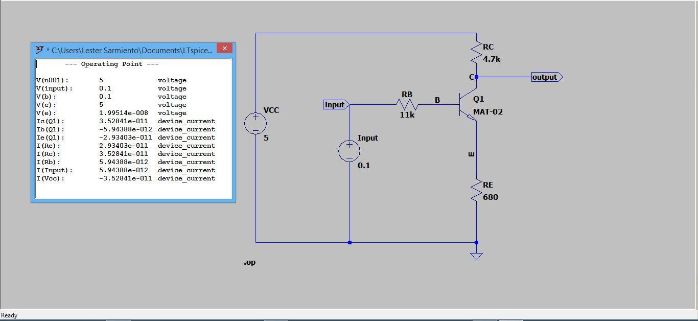
Now, the question is Using the DC operating point simulation, get the needed values by varying the input voltage. Compute for VBE, VCE, and VCB using the simulated values of VB, VC, and VE.

+ VCC 5 .op [SURNAME, FIRST NAME, MI] STUDENT NUMBER: 20XX-XXXXX-XX-X BJT DC ANALYSIS Input Input 2 RB 11k B RC 4.7k Q1 MAT-02 RE 680 Output + VCC 5 .op [SURNAME, FIRST NAME, MI] STUDENT NUMBER: 20XX-XXXXX-XX-X BJT DC ANALYSIS Input Input 2 RB 11k B RC 4.7k Q1 MAT-02 RE 680 Output
Step by Step Solution
3.49 Rating (162 Votes )
There are 3 Steps involved in it
Please see the below solution I have performed the experiment and got all the resu... View full answer

Get step-by-step solutions from verified subject matter experts