

Question: Given the ER diagram in Figure 1. Design a corresponding relational database schema from the ER diagram in Figure 1. Use the method discussed in
Given the ER diagram in Figure 1.
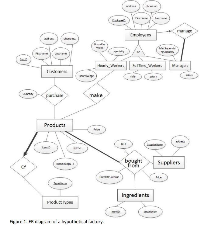
Design a corresponding relational database schema from the ER diagram in Figure 1. Use the method discussed in class to convert ER notations to relations while minimizing unnecessary redundancy and unnecessary relations. Implement as many constraints given in the ER diagram as possible.
a) Provide a script of SQL DDL statements. The relation names and attribute names should be meaningful for ease of understanding and maintenance of the database over time. The script must drop any existing tables of the same names before creating new ones.
b) Provide a script of SQL DML statements to add at least four rows of data of your choice into each table, but the data must satisfy all the constraints. The script must delete any of the existing rows before the insertion.
c) Write down all the constraints in the ER diagram in Figure 1 that cannot be enforced using relational database design (i.e., the use of relation schemas, primary key, foreign key, not null, and unique constraints).
Figure 1: ER diagram of a hypothetical factory. Figure 1: ER diagram of a hypothetical factory
Step by Step Solution
There are 3 Steps involved in it

Get step-by-step solutions from verified subject matter experts