Answered step by step
Verified Expert Solution
Question
1 Approved Answer
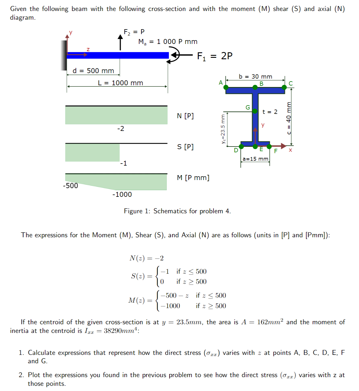
Given the following beam with the following cross-section and with the moment (M) shear (S) and axial (N) diagram. F = P Ma =

Given the following beam with the following cross-section and with the moment (M) shear (S) and axial (N) diagram. F = P Ma = 1 000 P mm F1 = 2P d = 500 mm L= 1000 mm N [P] -2 S [P] -1 M [P mm] -500 -1000 A b = 30 mm B y= 23.5 mm | G t = 2 y F a=15 mm c = 40 mm C Figure 1: Schematics for problem 4. The expressions for the Moment (M), Shear (S), and Axial (N) are as follows (units in [P] and [Pmm]): N(2) = 2 S(z) M(z): if z 500 -1 = if z 500 -500 - z -1000 if 500 = if z 500 If the centroid of the given cross-section is at y = 23.5mm, the area is A = 162mm and the moment of inertia at the centroid is Ixx = 38290mm 4: 1. Calculate expressions that represent how the direct stress (xx) varies with z at points A, B, C, D, E, F and G. 2. Plot the expressions you found in the previous problem to see how the direct stress (xx) varies with z at those points.
Step by Step Solution
★★★★★
3.33 Rating (150 Votes )
There are 3 Steps involved in it
Step: 1
1 To calculate the expressions that represent how the direct stress xx varies with z at points A B C ...
Get Instant Access to Expert-Tailored Solutions
See step-by-step solutions with expert insights and AI powered tools for academic success
Step: 2

Step: 3

Ace Your Homework with AI
Get the answers you need in no time with our AI-driven, step-by-step assistance
Get Started


