

Question
Given the following two-digit counter with decimal output block diagram which is shown in Figure 14. Figure 14. Figure 14. Block diagram of 2-digit counter
Given the following two-digit counter with decimal output block diagram which is shown in Figure 14.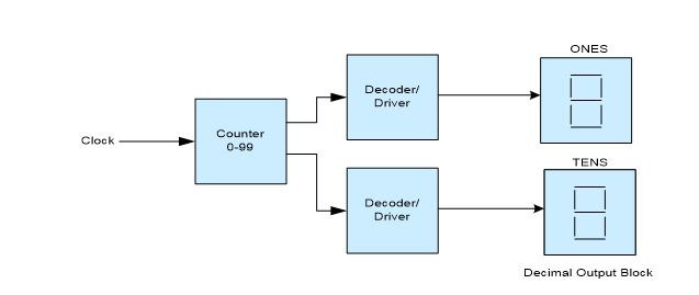 Figure 14.
Figure 14. Block diagram of 2-digit counter with decimal output
A. If the 7-segment displays read decimal 85, specify the BCD code between the counter and decoders.
B, Refer to the data sheet for 74147 encoder IC (ONLINE) . If only input 7 of the 74147 encoder is low, what is the logic state at each of the four outputs?
C. Refer to the data sheet for 74147 encoder IC(ONLINE). If both inputs 2 and 8 go LOW on the 74147 encoder, what is the logic state at each of the four outputs
D. Refer to the 7447 IC data sheet (ONLINE) and the 7-segment display device. If segments a, c, d, f and g are lit
What is the expected decimal number that will appear on the 7-segment display?
What are the input requirements for the 7447 IC to produce this number?
E. Refer to the 7447 IC data sheet.(ONLINE) If the BCD input to the decoder/drive is 1000
Which segments on the display will light?
What decimal number will be shown on the 7-segment display device?
ONES Decoder/ Driver Counter 0-99 Clock TENS Decoder Driver Decimal Output Block
Step by Step Solution
There are 3 Steps involved in it
Step: 1

Get Instant Access to Expert-Tailored Solutions
See step-by-step solutions with expert insights and AI powered tools for academic success
Step: 2

Step: 3
Ace Your Homework with AI
Get the answers you need in no time with our AI-driven, step-by-step assistance
Get Started
Essentials of Database Management
Authors: Jeffrey A. Hoffer, Heikki Topi, Ramesh Venkataraman
1st edition
133405680, 9780133547702 , 978-0133405682