

Question: Given the T-beam and cross-section shown in the figure below: a. Draw the overall free body diagram for beam b. Find the reaction forces
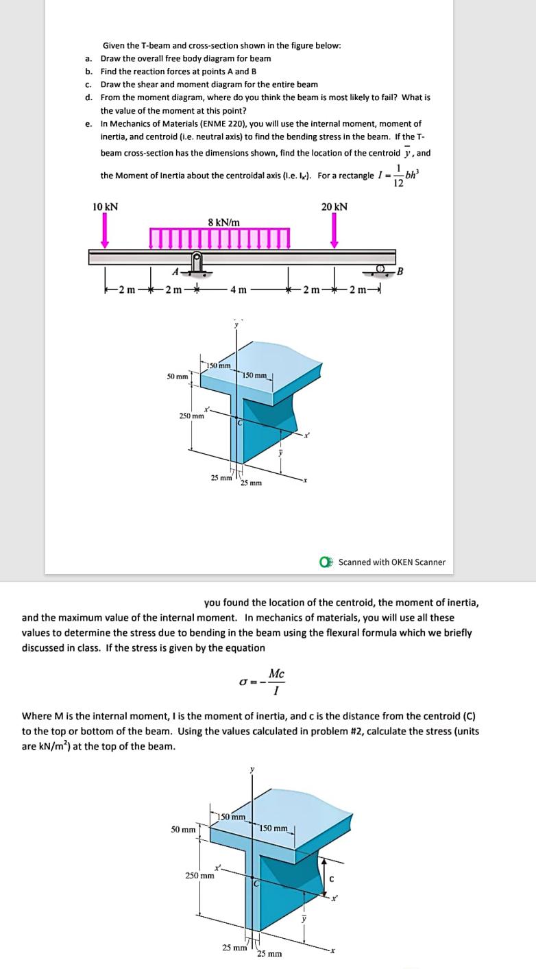
Given the T-beam and cross-section shown in the figure below: a. Draw the overall free body diagram for beam b. Find the reaction forces at points A and B c. Draw the shear and moment diagram for the entire beam d. From the moment diagram, where do you think the beam is most likely to fail? What is the value of the moment at this point? e. In Mechanics of Materials (ENME 220), you will use the internal moment, moment of inertia, and centroid (i.e. neutral axis) to find the bending stress in the beam. If the T- beam cross-section has the dimensions shown, find the location of the centroid y, and the Moment of Inertia about the centroidal axis (I.e. I). For a rectangle I -- bh = 10 kN -2m-2m- 50 mm 250 mm 8 kN/m 50 mm 4 m 150 mm 25 mm 150 mm 250 mm 25 mm you found the location of the centroid, the moment of inertia, and the maximum value of the internal moment. In mechanics of materials, you will use all these values to determine the stress due to bending in the beam using the flexural formula which we briefly discussed in class. If the stress is given by the equation J--- Mc I 150 mm 25 mm Where M is the internal moment, I is the moment of inertia, and c is the distance from the centroid (C) to the top or bottom of the beam. Using the values calculated in problem #2, calculate the stress (units are kN/m) at the top of the beam. 20 KN 150 mm -2m-2m- 25 mm -B O Scanned with OKEN Scanner C
Step by Step Solution
There are 3 Steps involved in it
The detailed ... View full answer

Get step-by-step solutions from verified subject matter experts