Answered step by step
Verified Expert Solution
Question
1 Approved Answer
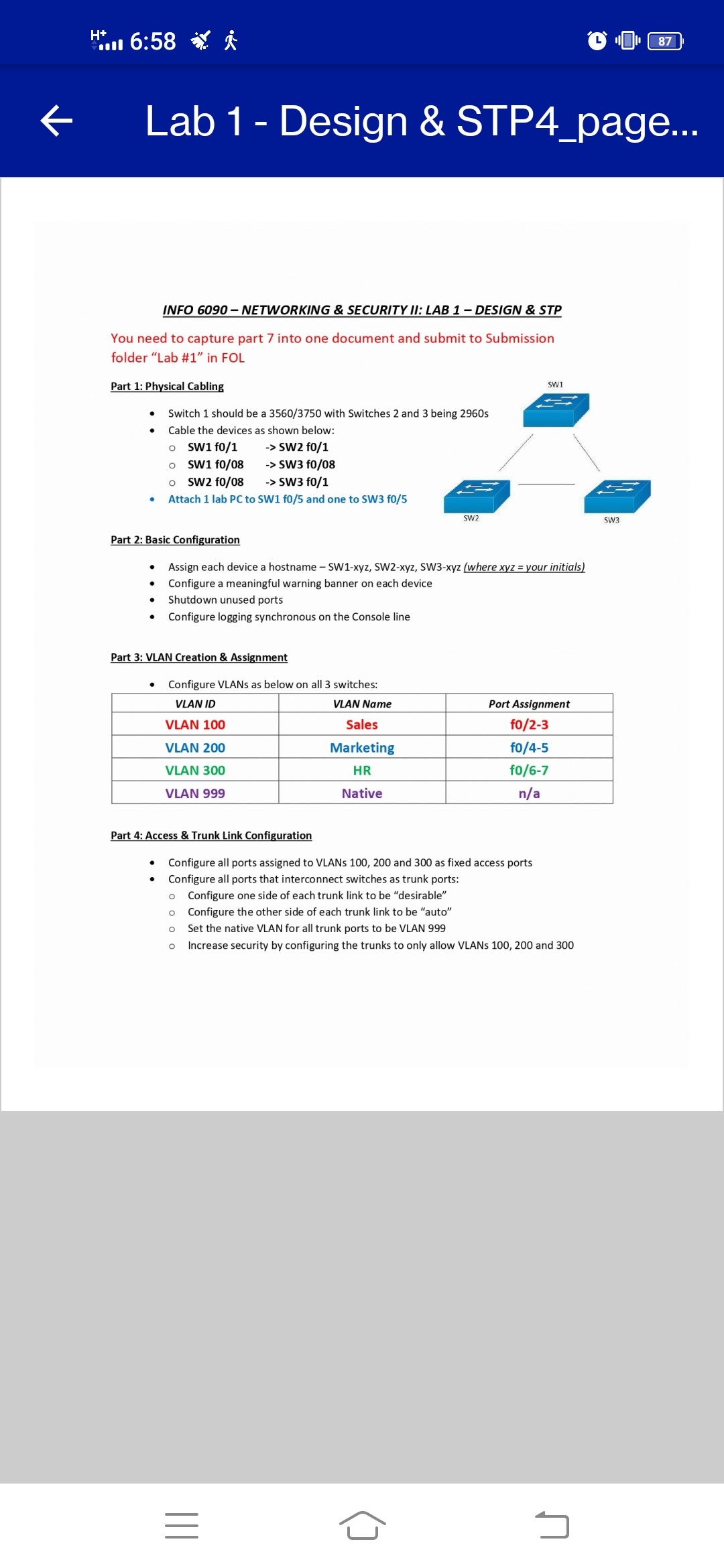
H+ 6:58 87 Lab 1 - Design & STP4_page... INFO 6090- NETWORKING & SECURITY II: LAB 1 - DESIGN & STP You need to


H+ 6:58 87 Lab 1 - Design & STP4_page... INFO 6090- NETWORKING & SECURITY II: LAB 1 - DESIGN & STP You need to capture part 7 into one document and submit to Submission folder "Lab #1" in FOL Part 1: Physical Cabling SW1 Switch 1 should be a 3560/3750 with Switches 2 and 3 being 2960s Cable the devices as shown below: SW1 f0/1 -> SW2 f0/1 SW1 f0/08 -> SW3 f0/08 SW2 f0/08 -> SW3 f0/1 Attach 1 lab PC to SW1 f0/5 and one to SW3 f0/5 SW2 Part 2: Basic Configuration Assign each device a hostname - SW1-xyz, SW2-xyz, SW3-xyz (where xyz = your initials) Configure a meaningful warning banner on each device . Shutdown unused ports Configure logging synchronous on the Console line Part 3: VLAN Creation & Assignment Configure VLANs as below on all 3 switches: VLAN ID VLAN 100 VLAN 200 VLAN 300 VLAN 999 VLAN Name Port Assignment Sales Marketing f0/2-3 f0/4-5 HR Native f0/6-7 n/a Part 4: Access & Trunk Link Configuration Configure all ports assigned to VLANs 100, 200 and 300 as fixed access ports Configure all ports that interconnect switches as trunk ports: Configure one side of each trunk link to be "desirable" o Configure the other side of each trunk link to be "auto" Set the native VLAN for all trunk ports to be VLAN 999 Increase security by configuring the trunks to only allow VLANs 100, 200 and 300 ||| SW3 J H+ --- 6:58 87 Lab 1 - Design & STP4_page... Part 5: Rapid Spanning Tree Configure all switches to participate in rapid spanning tree Configure Switch 1 to be the root primary for all VLANs except VLAN 300 Configure Switch 1 to be the root secondary for VLAN 300 Configure Switch 2 to be the root primary for VLAN 300 and the root secondary for all other VLANs Identify the port types on all 3 switches Part 6: Multiple Spanning Tree (Optional if using Packet Tracer) Configure all switches to participate in MSTP region "CCNP" Add a revision number 10 Create 2 instances: o 1 for VLANs 100 & 200 o 2 for VLAN 300 Part 7: Submission Capture the command below on all devices: o Show vlan brief o Show spanning-tree summary o Show interface trunk o Show interface status Part 8: Teardown (Optional if using Packet Tracer) Erase all data and reload the switches: o Delete vla.dat Erase startup-config o Reload ||| J
Step by Step Solution
There are 3 Steps involved in it
Step: 1

Get Instant Access to Expert-Tailored Solutions
See step-by-step solutions with expert insights and AI powered tools for academic success
Step: 2

Step: 3

Ace Your Homework with AI
Get the answers you need in no time with our AI-driven, step-by-step assistance
Get Started


