

Answered step by step
Verified Expert Solution
Question
1 Approved Answer
he wants a code in number 2, for pic18f4580 1. Complete the schematic below showing how to connect on a PIC: (a) a pushbutton PB
he wants a code in number 2, for pic18f4580
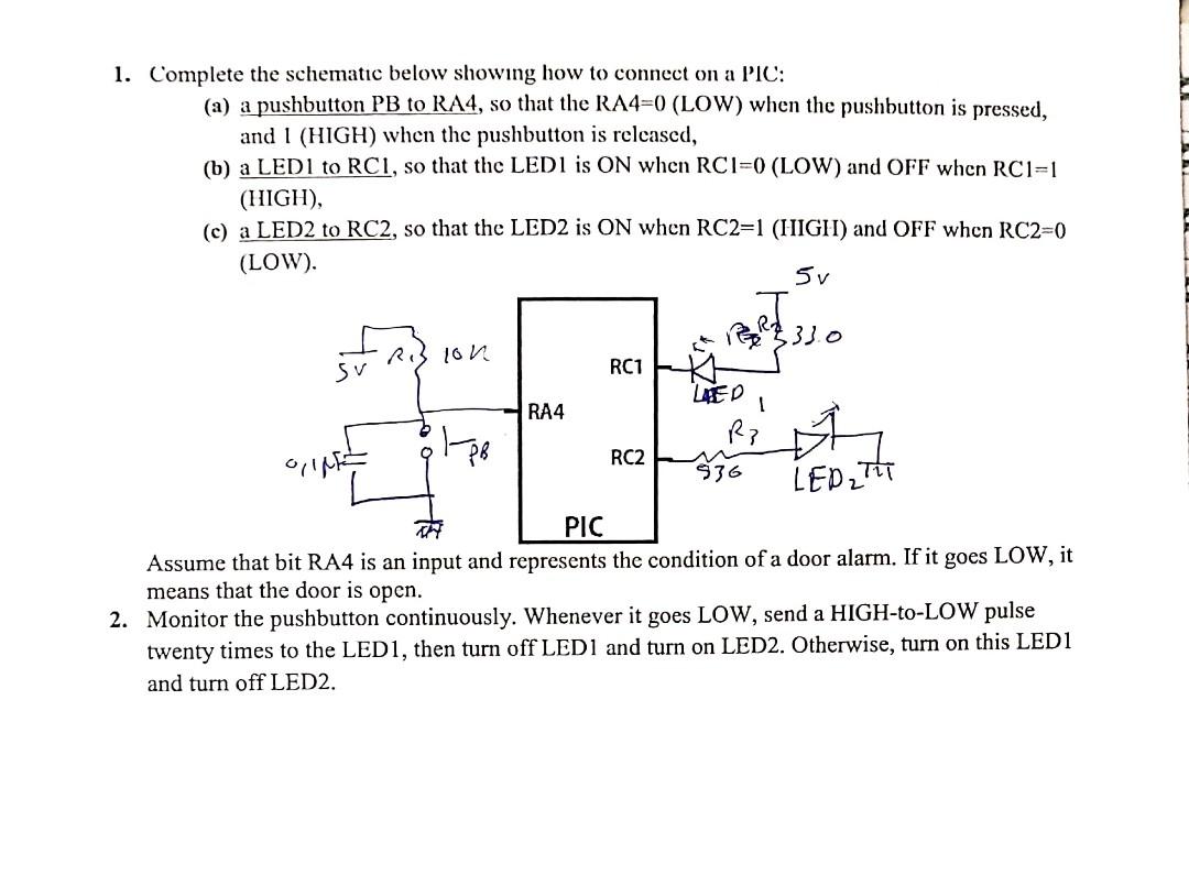
1. Complete the schematic below showing how to connect on a PIC: (a) a pushbutton PB to RA4, so that the RA4=0 (LOW) when the pushbutton is pressed, and I (HIGH) when the pushbutton is released, (b) a LEDI to RC1, so that the LEDI is ON when RCI=0 (LOW) and OFF when RC1=1 (HIGH), (c) a LED2 to RC2, so that the LED2 is ON when RC2=1 (HIGH) and OFF when RC2=0 (LOW). 5v lon REAL 333 Sv RC1 LED RA4 Rp RC2 536 LED2 TIT PIC Assume that bit RA4 is an input and represents the condition of a door alarm. If it goes LOW, it means that the door is open. 2. Monitor the pushbutton continuously. Whenever it goes LOW, send a HIGH-to-LOW pulse twenty times to the LED1, then turn off LED1 and turn on LED2. Otherwise, turn on this LED1 and turn off LED2
Step by Step Solution
There are 3 Steps involved in it
Step: 1

Get Instant Access to Expert-Tailored Solutions
See step-by-step solutions with expert insights and AI powered tools for academic success
Step: 2

Step: 3
Ace Your Homework with AI
Get the answers you need in no time with our AI-driven, step-by-step assistance
Get Started
Spatial Database Systems Design Implementation And Project Management
Authors: Albert K.W. Yeung, G. Brent Hall
1st Edition
1402053932, 978-1402053931