Question: Hello, please, I want to learn to solve all these questions step by step and thank you 5 Problems: 1. For the ladder diagram rung
Hello, please, I want to learn to solve all these questions step by step and thank you
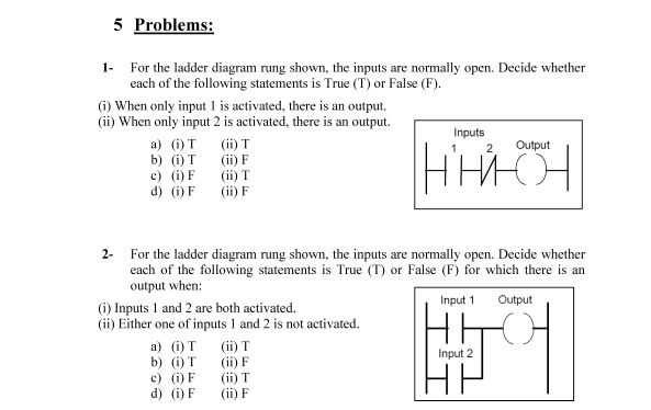
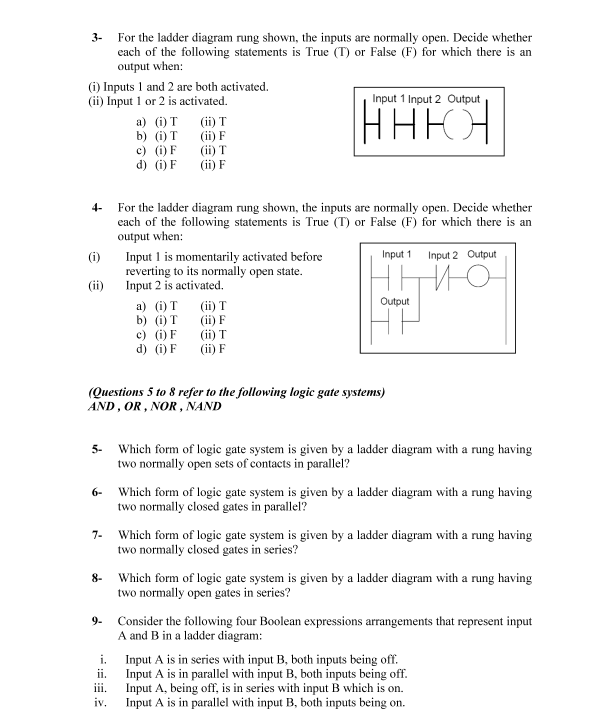
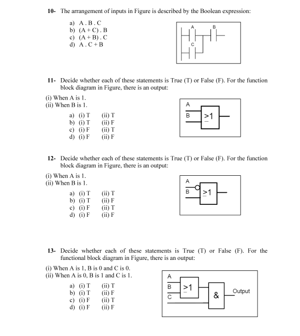
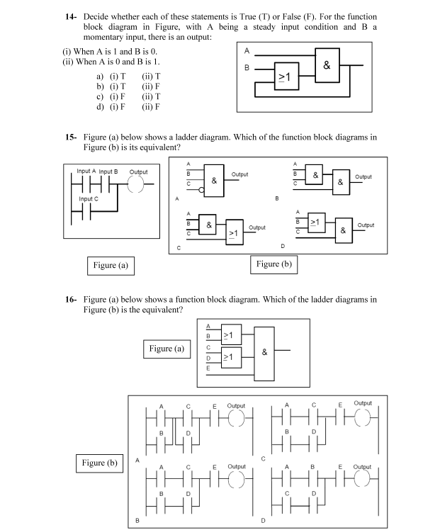
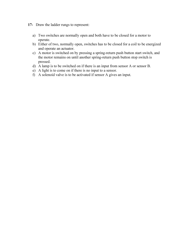
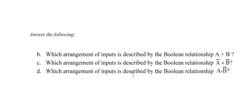
5 Problems: 1. For the ladder diagram rung shown, the inputs are normally open. Decide whether each of the following statements is True (T) or False (F). (0When only input I is activated, there is an output. (ii) When only input 2 is activated, there is an output. Inputs a) OT (ii) T Output b) ( OT (ii) F c) (i) F (ii) T d) (0) F (ii) F HHH OH 2- For the ladder diagram rung shown, the inputs are normally open. Decide whether each of the following statements is True (T) or False (F) for which there is an output when: (i) Inputs 1 and 2 are both activated. Input 1 Output (ii) Either one of inputs 1 and 2 is not activated. a) () T (1) T b) () T (ii) F Input 2 c) () F (ii) T d) (i) F (ii) F rot For the ladder diagram rung shown, the inputs are normally open. Decide whether each of the following statements is True (T) or False (F) for which there is an output when: (1) Inputs 1 and 2 are both activated. (ii) Input 1 or 2 is activated. Input 1 Input 2 Output a) OT (1) T b) () (ii) c) (i) F (1) T d) OF (ii) F HHEOL (i) (ii) For the ladder diagram rung shown, the inputs are normally open. Decide whether each of the following statements is True (T) or False (F) for which there is an output when: Input 1 is momentarily activated before Input 1 Input 2 Output reverting to its normally open state. Input 2 is activated. a) (i) T Output b) (i) T (ii) F c) (i) F (ii) T d) (i) F (ii) F (ii) T (Questions 5 to 8 refer to the following logic gate systems) AND, OR, NOR, NAND 5- Which form of logic gate system is given by a ladder diagram with a rung having two normally open sets of contacts in parallel? 6- Which form of logic gate system is given by a ladder diagram with a rung having two normally closed gates in parallel? 7- Which form of logic gate system is given by a ladder diagram with a rung having two normally closed gates in series? 8- Which form of logic gate system is given by a ladder diagram with a rung having two normally open gates in series? 9. Consider the following four Boolean expressions arrangements that represent input A and B in a ladder diagram: i. Input A is in series with input B, both inputs being off. ii. Input A is in parallel with input B, both inputs being off. iii. Input A, being off, is in series with input B which is on. iv. Input A is in parallel with input B, both inputs being on. 10- The arrangement of inputs in Figure is described by the Boolean expression: a) A.B.C b) (A+C).B c) (A + B). d) A.C+B A B 11- Decide whether each of these statements is True (T) or False (F). For the function block diagram in Figure, there is an output: (1) When A is 1. (ii) When Bis 1. a) (0) T (ii) T >1 b) (i) T (1) F c) () F (ii) d) (0) (ii) F B A 12- Decide whether each of these statements is True (T) or False (F). For the function block diagram in Figure, there is an output: (1) When A is 1. (ii) When Bis 1. a) () T (ii) T >1 b) () T (ii) c) () F (ii) d) (i) F (ii) 13- Decide whether cach of these statements is True (T) or False (F). For the functional block diagram in Figure, there is an output: (1) When A is 1, B is 0 and C is 0. (ii) When A is 0, B is 1 and C is 1. a) () T (ii) T B >1 b) (i) T (ii) Output c) () F (ii) T & d) (0) (ii) F 14- Decide whether each of these statements is True (T) or False (F). For the function block diagram in Figure, with A being a steady input condition and B a momentary input, there is an output: (1) When A is 1 and B is 0. (ii) When A is 0 and B is 1. & a) () () T >1 b) (i) T (ii) F c) () F (1) T d) (0) F (ii) F B 15- Figure (a) below shows a ladder diagram. Which of the function block diagrams in Figure (b) is its equivalent? Input A Input B Output Output & Output Input C & 21 Output Output D Figure (a) Figure (b) 16- Figure (a) below shows a function block diagram. Which of the ladder diagrams in Figure (b) is the equivalent? B >1 Figure (a) C & D 1 E E Output Output 4707 B D ito Figure (b) Output Output ito ito B D 17- Draw the ladder rungs to represent: a) Two switches are normally open and both have to be closed for a motor to operate. b) Either of two, normally open, switches has to be closed for a coil to be energized and operate an actuator. c) A motor is switched on by pressing a spring-return push button start switch, and the motor remains on until another spring-return push button stop switch is pressed d) A lamp is to be switched on if there is an input from sensor A or sensor B. e) A light is to come on if there is no input to a sensor. f) A solenoid valve is to be activated if sensor A gives an input. Answer the following: b. Which arrangement of inputs is described by the Boolean relationship A + B ? c. Which arrangement of inputs is described by the Boolean relationship +B? d. Which arrangement of inputs is described by the Boolean relationship A:B
Step by Step Solution
There are 3 Steps involved in it

Get step-by-step solutions from verified subject matter experts


