Question
Hello, this is will be all my configuration, given by my lecture for this IP address below (refer to Figure 1) Given address range Subnet
Hello, this is will be all my configuration, given by my lecture for this IP address below (refer to Figure 1)
| Given address range | Subnet address to Internet router | Admin | Remote Sale | Engrg | Max server | OSPF Process ID |
| 201.30.10.0/24 | 220.220.200.0/30 | 40 | 20 | 16 | 3 | 70 |
Figure 1
Before I do anything, I had labeled them using Fa0/0, Fa0/1, S0/0/0 & S0/0/1 interfaces so that I won't be so confusing when I implement in Packet Tracer (Refer to Figure 2) & This is my completed implemented on Packet Tracer (Refer to Figure 3)
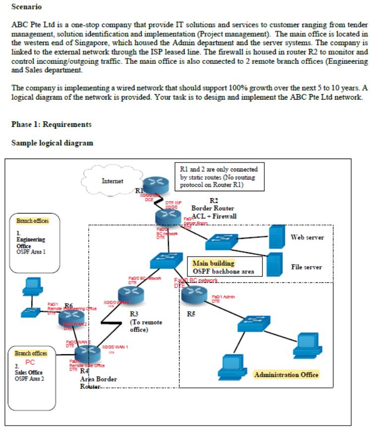
Figure 2
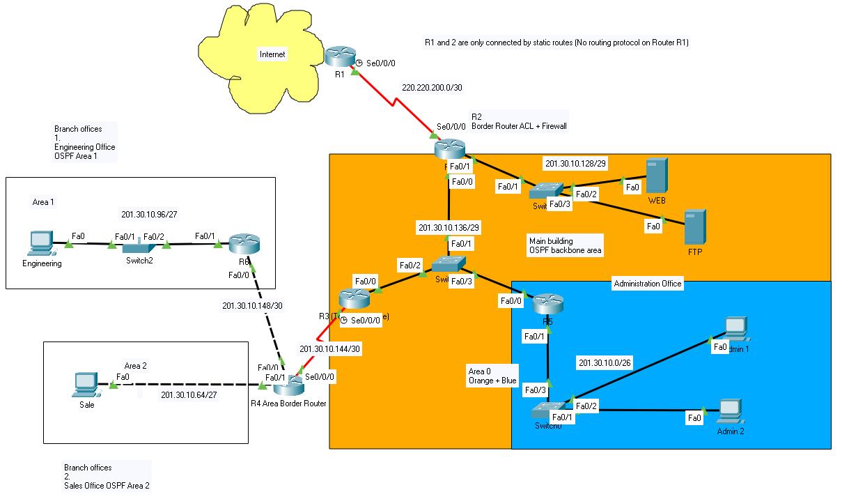
Figure 3
I had filled in VSLM in the table accordingly below image (Refer to Figure 4)
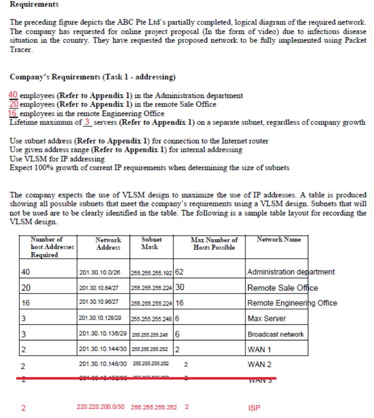
Figure 4
For this image below (Refer to Figure 5), the question had ask me fill in inside the table, and so I finished up the requirement in the excel sheet (Refer to Figure 6)
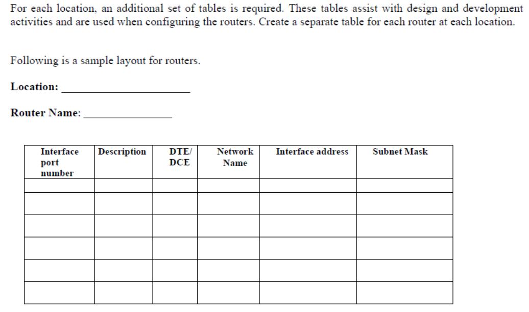
Figure 5
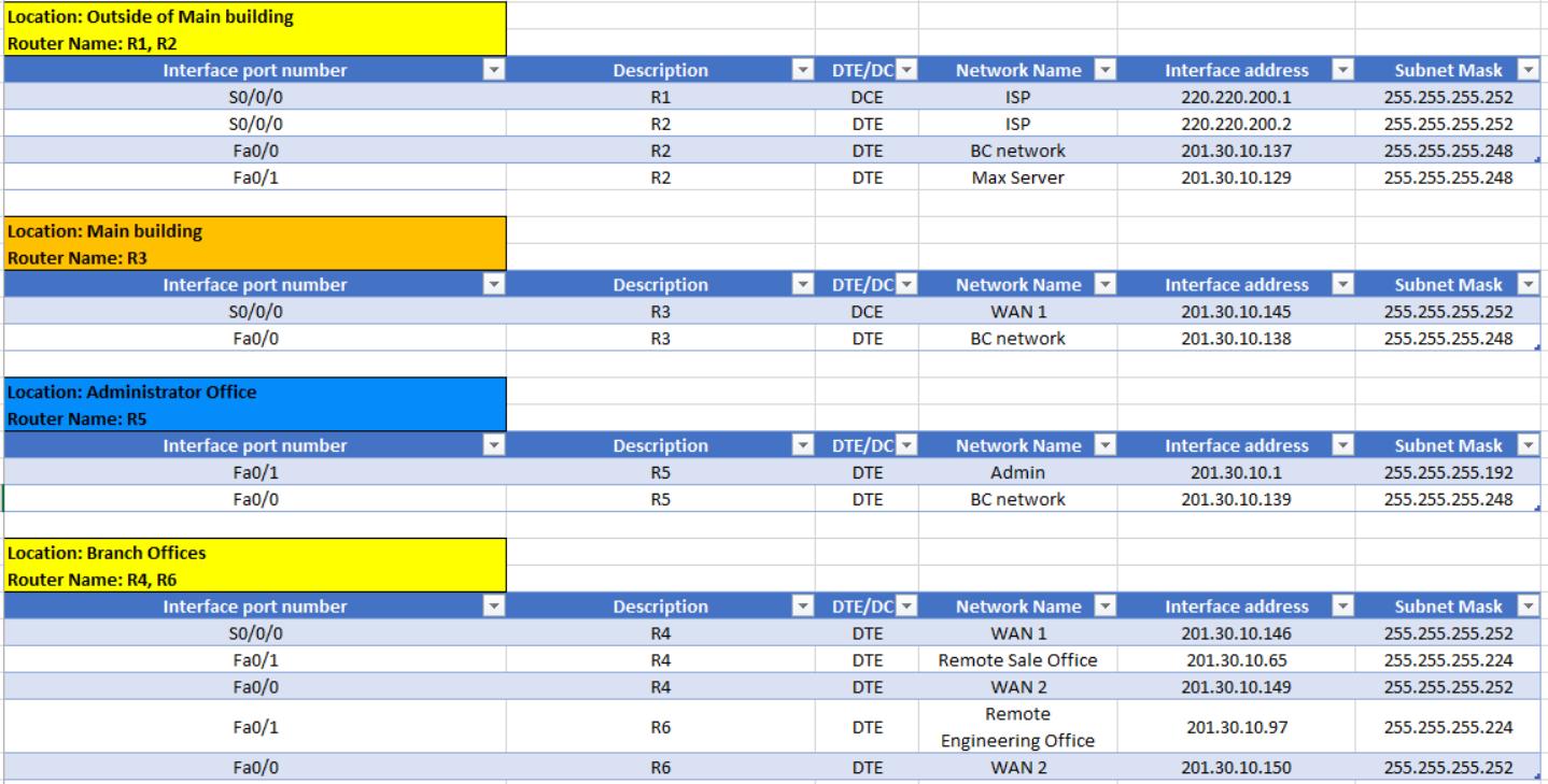
Figure 6
Now is the main question, while I reading these requirements, I had manged to configured all the interfaces on routers & PC, one thing I stuck is, where can i disable routing updates on which Router? Which loopback address for router ID on which router? How to ensure I can have redundancy for ISP, for Router R7 and another ISP Link & lastly, how do I set Hello and Dead time interval for serial interface, 20 seconds and 80 seconds. (Refer to Figure 7). Please refer to Figure 8 which all the commands I have preparation before I add the remaining commands inside (Green color mean I added the commands inside the router already)
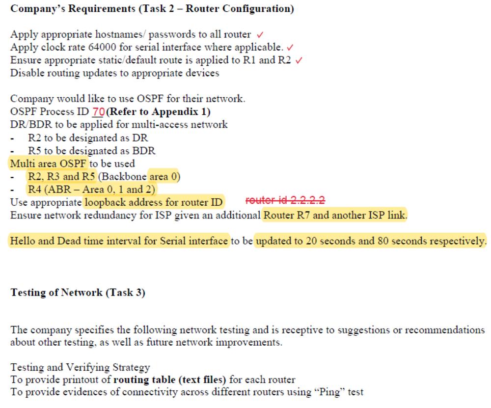
Figure 7

Figure 8
All these commands I got the helps from my friends & lecturer, hopefully this will help me clear out my doubt and fulfill the question on above. Do check if my commands for this table (Refer to Figure 8) is in correct word.
Scenario ABC Pte Ltd is a one-stop company that provide IT solutions and services to customer ranging from tender management, solution identification and implementation (Project management). The main office is located in the western end of Singapore, which housed the Admin department and the server systems. The company is linked to the external network through the ISP leased line. The firewall is housed in router R2 to monitor and control incoming/outgoing traffic. The main office is also connected to 2 remote branch offices (Engineering and Sales department. The company is implementing a wired network that should support 100% growth over the next 5 to 10 years. A logical diagram of the network is provided. Your task is to design and implement the ABC Pte Ltd network. Phase 1: Requirements Sample logical diagram Branch offices 1. Engineering Office OSPF Area 1 FR6g 0 Remote Branch offices PC 2. Sales Office OSPF Area 2 UWANZI OTE FaWAN Remote OTE R Internet 8000 80:00 WAN 1 Office Area Border Router RI 8000 DCE Fadi BC work DTE Fabio Betwork OTE R3 (To remote office) R1 and 2 are only connected by static routes (No routing protocol on Router R1) DTE ISP 6000 R2 Border Router FACL+Firewall SevelBar Main building OSPF backbone area FabLBC networks.. DIE R5 Fa0/1 Admin OTE Web server File server Administration Office
Step by Step Solution
There are 3 Steps involved in it
Step: 1

Get Instant Access to Expert-Tailored Solutions
See step-by-step solutions with expert insights and AI powered tools for academic success
Step: 2

Step: 3

Ace Your Homework with AI
Get the answers you need in no time with our AI-driven, step-by-step assistance
Get Started


