Answered step by step
Verified Expert Solution
Question
1 Approved Answer
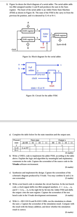
Help to give the full solution and answer with the VHDL code. Figure 5 a shows the tileck diapram of a serial adder. The serial
Help to give the full solution and answer with the VHDL code.
Figure a shows the tileck diapram of a serial adder. The serial adder ialds
two gbar unsignod rumber A iad and probuces the sum in the Sum
regiser. The heart of the serial wdder is in Adder Finite Stawe Mockhine
FSM as stown in Flgure th The sale of the FSM is the caeryin from the
previous bit position, and it is drenotod by
Figure a: Bhock diaggam for the sirial adber.
Figure b: Circuit for the adice FSM
a Coeplete the tahle below for the stawe transition iad the cutpos sum.
marks
B Write a VHD cose to implement the addor FSM arcoeding to the table
above Explain the bgic and algorithes try meseingful and explanatory
cometents in the code. Capture the screentiont of the source code in the
Vivabo software etwimonment.
marks
c Syuthusize and implement the design. Captume the screeminnts of the
shematic diagriet probured by Vivalo. You may combine b and c in
cele screcestost.
d Write a west bentich cose to simulate the circuit furction. In the west berich
cobe, a clock sigral shifs two thit unsigned rumbers,
and to the right bit by tir linto the AdSer FSM and shifts
the outper s into the sumregisier. Capoure the seroershos of the trost
berch oode in the Vivalo developencent emircetment.
e With and run the simulation to obtain
the sum s Copture the screntishot of the simularion result. Coenpare with
the wsult with the binary wddition, and show whothof the simulation
result is carrect.

Step by Step Solution
There are 3 Steps involved in it
Step: 1

Get Instant Access to Expert-Tailored Solutions
See step-by-step solutions with expert insights and AI powered tools for academic success
Step: 2

Step: 3

Ace Your Homework with AI
Get the answers you need in no time with our AI-driven, step-by-step assistance
Get Started


