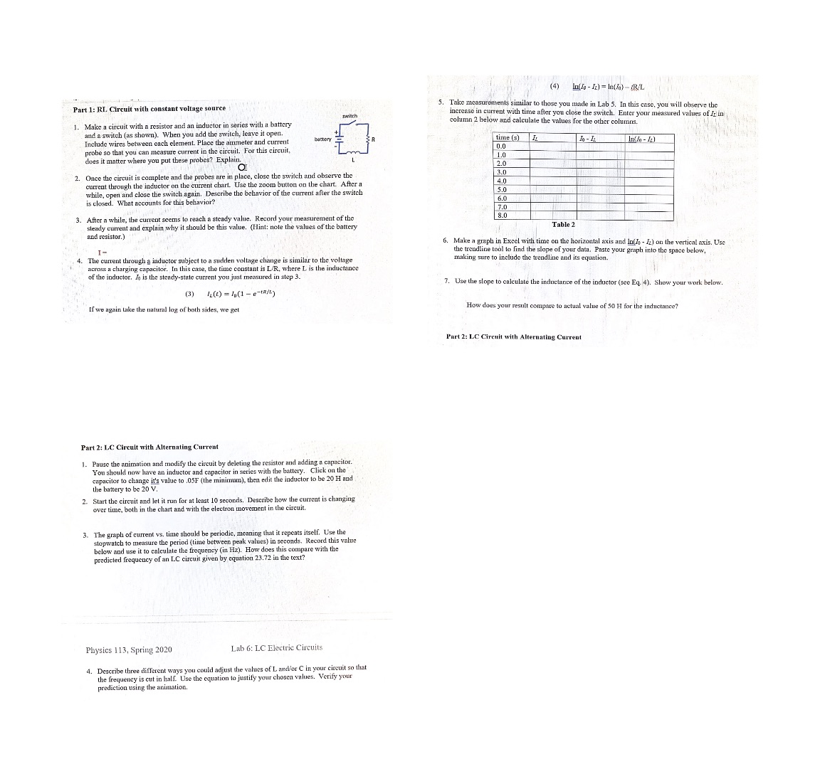
Question: Help with physics lab. Link to stimulation: https://phet.colorado.edu/sims/html/circuit-construction-kit-ac/latest/circuit-construction-kit-ac_en.htmlPicture might be a little blurry but it should be clear when zoomed in. Please don't switch out
Help with physics lab. Link to stimulation: https://phet.colorado.edu/sims/html/circuit-construction-kit-ac/latest/circuit-construction-kit-ac_en.htmlPicture might be a little blurry but it should be clear when zoomed in. Please don't switch out the seconds in the table, use the exact information and instructions provided please and thank you.

(4) In(Jo - 12) = In(6)-R/L Part 1: RI. Circuit with constant voltage source 5. Take measurements similar to those you made in Lab 5. In this case, you will observe the increase in current with time after you close the switch. Enter your measured values of Ir in Make a circuit with a resistor and an inductor in series with a battery column 2 below and calculate the values for the other columns. and a switch (as shown). When you add the switch, leave it open. Include wires between each element. Place the ammeter and current time (9) IL probe so that you can measure current in the circuit, For this circuit, 0.0 does it matter where you put these probes? Explain. 1.0 2.0 2. Once the circuit is complete and the probes are in place, close place, close the switch and observe the 3.0 current through the inductor on the current chart. Use the zoom button on the chart. After a 4.0 while, open and close the switch again. Describe the behavior of the current after the switch 5.0 is closed. Wh 6.0 After a while, the current seems to reach a steady value. Record your measurement of the claim why it should be this value. (Hint: note the values of the battery steady current and explain why it should Table 2 and resistor.) I- 6. Make a graph in Excel with time on the horizontal axis and lo(do - 12) on the vertical axis. Use the trendline tool to find the slope of your data. Paste your graph into the space below, 4. The current through a inductor subject to a sudden voltage change is similar to the voltage making sure to include the trendline and its equation. across a charging capacitor. In this case, the time constant is L'R. where L is the inductance of the inductor. Jo is the steady-state current you just measured in step 3. 7. Use the slope to calculate the inductance of the inductor (see Eq. 4). Show your work below. (3) h() = (1 -e-tR/[) If we again take the natural log of both sides, we get How does your result compare to actual value of 50 H for the inductance? Part 2: LC Circuit with Alternating Current Part 2: LC Circuit with Alternating Current . Pause the animation and modify the circuit by deleting the resistor and adding a capacitor. You should now have an inductor and capacitor in series with the battery. Click on the apacitor to change it's value to .05F (the minimum), then edit the inductor to be 20 H and the battery to be 20 v. 2. Start the circuit and let it run for at least 10 seconds. Describe how the current is changing over time, both in the chart and with the electron movement in the circuit. 3. The graph of current vs. time should be periodic, meaning that it repeats itself. Use the stopwatch to measure the period (time between peak values) in seconds, Record this value below and use it to calculate the frequency (in Hz). How does this compare with the predicted frequency of an LC circuit given by equation 23.72 in the text? Physics 113, Spring 2020 Lab 6: LC Electric Circuits 1. Describe three different ways you could adjust the values of L and/or C in your circuit so that the frequency is cut in half. Use the equation to justify your chosen values. Verify your prediction using the animation
Step by Step Solution
There are 3 Steps involved in it

Get step-by-step solutions from verified subject matter experts


