Question
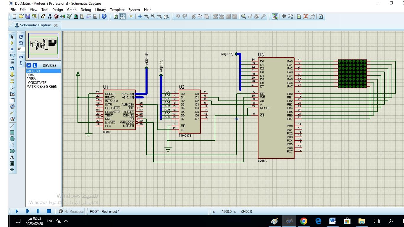
here circuit diagram for interface Dot-matrix LED display 1- Here is the assembly language code for the circuit shown in the picture. Explain the design
here circuit diagram for interface Dot-matrix LED display

1- Here is the assembly language code for the circuit shown in the picture. Explain the design and code, line by line, and fix errors, if any. 2- There is a problem when displaying the result in the PROTEUS program, as there may be a small error in the circuit or the code. 3- Write a report on this design including a summary, introduction, body of report, and conclusion
CODE SEGMENT
ASSUME CS:CODE,DS:CODE ;
PPIC_C EQU 06H ;control register
PPIC EQU 04H ;c port
PPIB EQU 02H
PPIA EQU 00H ;
ORG 0000H
MOV AL,10000000B
OUT PPIC_C,AL
;
L1: MOV SI,OFFSET FONT
;
MOV AH, 11111110B
;
L2: MOV AL,AH
OUT PPIB,AL
MOV AL,BYTE PTR CS:[SI]
OUT PPIA,AL
;
CALL TIMER
MOV AL,00H
OUT PPIA,AL
INC SI
CLC
ROL AH,1
JC L2
JMP L1
;
INT 3
;
TIMER: MOV CX,250
TIMER1:
NOP
NOP
NOP
NOP
LOOP TIMER1
RET
;
FONT:
DB 00000000B
DB 11111100B
DB 00010010B
DB 00010001B
DB 00010001B
DB 00010010B
DB 11111100B
DB 00000000B
CODE ENDS
END
MOV AL,BL
OUT PPIB,AL
CALL DELAY
ROL BL,1;
JMP L1
DELAY:MOV CX,11111111111111B
TIMER1:NOP
NOP
NOP
NOP
LOOP TIMER1
RET
;
CODE ENDS
END
---------------------------------------------------------------------------------------------------------------------------------------
I hope this time to get a clear answer to my question from chegg
Step by Step Solution
There are 3 Steps involved in it
Step: 1

Get Instant Access to Expert-Tailored Solutions
See step-by-step solutions with expert insights and AI powered tools for academic success
Step: 2

Step: 3

Ace Your Homework with AI
Get the answers you need in no time with our AI-driven, step-by-step assistance
Get Started


