Question
Here is the code provided (Only need code where it says finish up by doing the 2 for the digits #4 and #5 and make
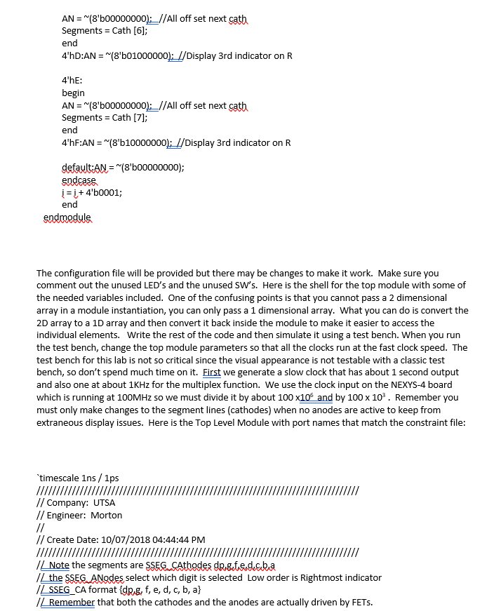
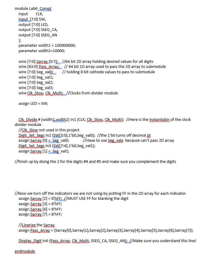
Here is the code provided (Only need code where it says "finish up by doing the 2 for the digits #4 and #5 and make sure you complement the digits").
module Lab6_Comp(
//input CLK,
//input [7:0] SW,
output [7:0] LED,
output [7:0] SSEG_CA,
output [7:0] SSEG_AN
);
parameter width1 = 100000000;
parameter width2=10000;
wire [7:0] Sarray [0:7]; //64 bit 2D array holding desired values for all digits
wire [63:0] Pass_Array; // 64 bit 1D array used to pass the 2D array to submodule
wire [7:0] Seg_val0; // holding 8 bit cathode values to pass to submodule
wire [7:0] Seg_val1;
wire [7:0] Seg_val2;
wire [7:0] Seg_val3;
wire Clk_Slow, Clk_Multi; //Clocks from divider module
assign LED = SW;
Clk_Divide # (width1,width2) In1 (CLK, Clk_Slow, Clk_Multi); //Here is the instanitatin of the clock divider module
//Clk_Slow not used in this project
Digit_Set_Segs In2 (SW[3:0],1'b0,Seg_val0); //the 1'b0 turns off decimal pt
assign Sarray [0] = Seg_val0; //Have to use Seg_valx because can't pass 2D array
Digit_Set_Segs In3 (SW[7:4],1'b0,Seg_val1);
assign Sarray [1] = Seg_val1;
//finish up by doing the 2 for the digits #4 and #5 and make sure you complement the digits
//Now we turn off the indicators we are not using by putting FF in the 2D array for each indicator.
assign Sarray [2] = 8'hFF; //MUST USE FF for blanking the digit
assign Sarray [3] = 8'hFF;
assign Sarray [6] = 8'hFF;
assign Sarray [7] = 8'hFF;
//Linerize the Sarray
assign Pass_Array = {Sarray[0],Sarray[1],Sarray[2],Sarray[3],Sarray[4],Sarray[5],Sarray[6],Sarray[7]};
Display_Digit In6 (Pass_Array, Clk_Multi, SSEG_CA, SSEG_AN); //Make sure you understand this line!
endmodule
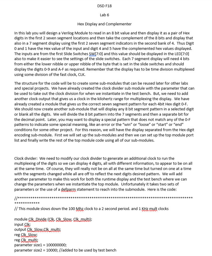
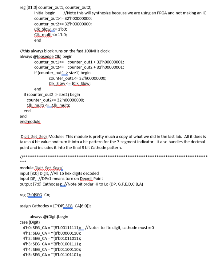
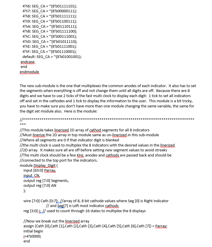
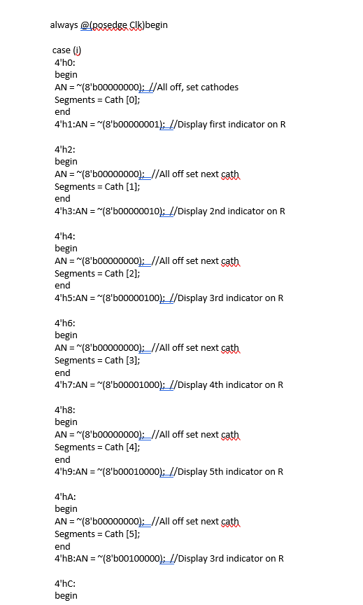
DSD F18 Lab 6 Hex Display and Complementer In this lab you wil design a Verilog Module to read in an 8 bit value and then display it as a pair of Hex digits in the first 2 seven segment locations and then take the complement of the 8 bits and display that also in a 7 segment display using the first 2 seven segment indicators in the second bank of 4. Thus Digit 0 and 1 have the Hex value of the input and digit 4 and 5 have the complemented hex values displayed The inputs are from the first Slide Switches SW[7:0] and this value should be displayed in the LED[7:0] also to make it easier to see the settings of the slide switches. Each 7 segment display will need 4 bits from either the lower nibble or upper nibble of the byte that is set in the slide switches and should display the digits 0-9 and A-F as required. Remember that the display has to be time division multiplexed using some division of the fast clock, CLK. The structure for the code will be to create some sub-modules that can be reused later for other labs and special projects. We have already created the clock divider sub module with the parameter that carn be used to take out the clock division for when we instantiate in the test bench. But, we need to add another clock output that gives us a clock in the kilohertz range for multiplexing the display. We have already created a module that gives us the correct seven segment pattern for each 4bit Hex digit O-F We should now create another sub-module that will display any 8 bit segment pattern in a selected digit or blank all the digits. We will divide the 8 bit pattern into the 7 segments and then a separate bit for the decimal point. Later, you may want to display a special pattern that does not match any of the 0-F patterns to indicate some special meaning, like an error or the "win" or "loose" or "start" or "end" conditions for some other project. For this reason, we wil have the display separated from the Hex digit encoding sub-module. First we will set up the sub-modules and then we can set up the top module port list and finally write the rest of the top module code using all of our sub-modules. Clock divider: We need to modify our clock divider to generate an additional clock to run the multiplexing of the digits so we can display 4 digits, all with different information, to appear to be on all at the same time. Of course, they will really not be on all at the same time but turned on one at a time with the segments changed while all are off to reflect the next digits desired pattern. We will add another parameter to make this work for both the runtime display and the test bench where we can change the parameters when we instantiate the top module. Unfortunately it takes two sets of parameters or the use of a defparm statement to reach into the submodule. Here is the code: ** ************** ****** ** ** ** // This module slows down the 100 Mhz clock to a 2 second period. and 1 KHz mult clocks module Clk Divide (Clk Clk Slow, Clkmulti); input Clk output ksley ASUs multi; reg Clk Slow reg Clk mult parameter size1-100000000; parameter size2 10000; //added to be used by test bench DSD F18 Lab 6 Hex Display and Complementer In this lab you wil design a Verilog Module to read in an 8 bit value and then display it as a pair of Hex digits in the first 2 seven segment locations and then take the complement of the 8 bits and display that also in a 7 segment display using the first 2 seven segment indicators in the second bank of 4. Thus Digit 0 and 1 have the Hex value of the input and digit 4 and 5 have the complemented hex values displayed The inputs are from the first Slide Switches SW[7:0] and this value should be displayed in the LED[7:0] also to make it easier to see the settings of the slide switches. Each 7 segment display will need 4 bits from either the lower nibble or upper nibble of the byte that is set in the slide switches and should display the digits 0-9 and A-F as required. Remember that the display has to be time division multiplexed using some division of the fast clock, CLK. The structure for the code will be to create some sub-modules that can be reused later for other labs and special projects. We have already created the clock divider sub module with the parameter that carn be used to take out the clock division for when we instantiate in the test bench. But, we need to add another clock output that gives us a clock in the kilohertz range for multiplexing the display. We have already created a module that gives us the correct seven segment pattern for each 4bit Hex digit O-F We should now create another sub-module that will display any 8 bit segment pattern in a selected digit or blank all the digits. We will divide the 8 bit pattern into the 7 segments and then a separate bit for the decimal point. Later, you may want to display a special pattern that does not match any of the 0-F patterns to indicate some special meaning, like an error or the "win" or "loose" or "start" or "end" conditions for some other project. For this reason, we wil have the display separated from the Hex digit encoding sub-module. First we will set up the sub-modules and then we can set up the top module port list and finally write the rest of the top module code using all of our sub-modules. Clock divider: We need to modify our clock divider to generate an additional clock to run the multiplexing of the digits so we can display 4 digits, all with different information, to appear to be on all at the same time. Of course, they will really not be on all at the same time but turned on one at a time with the segments changed while all are off to reflect the next digits desired pattern. We will add another parameter to make this work for both the runtime display and the test bench where we can change the parameters when we instantiate the top module. Unfortunately it takes two sets of parameters or the use of a defparm statement to reach into the submodule. Here is the code: ** ************** ****** ** ** ** // This module slows down the 100 Mhz clock to a 2 second period. and 1 KHz mult clocks module Clk Divide (Clk Clk Slow, Clkmulti); input Clk output ksley ASUs multi; reg Clk Slow reg Clk mult parameter size1-100000000; parameter size2 10000; //added to be used by test bench
Step by Step Solution
There are 3 Steps involved in it
Step: 1

Get Instant Access to Expert-Tailored Solutions
See step-by-step solutions with expert insights and AI powered tools for academic success
Step: 2

Step: 3

Ace Your Homework with AI
Get the answers you need in no time with our AI-driven, step-by-step assistance
Get Started


