Question
Hey, I have a lab report, for my Digital Logic class, that I am struggling a bit with. I have the report designed fairly well,
Hey, I have a lab report, for my Digital Logic class, that I am struggling a bit with. I have the report designed fairly well, and I have all of the code working, etc. My only issue is explaining how/why certain things are happening and answering the post-lab questions (I will post these at the bottom). Below I will include screenshots of: 1. Code from our Lab 1 (which is used in this lab). 2. Code from our Lab 2 (This lab)
3. Screenshots of all relevanteeded information for you to properly answer my question(s).
*All code and screenshots have been approved and are correct, in terms of assignment requirements*
--
Lab 1 Code (ex1 & ex2):
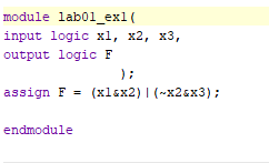
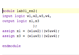
--
Lab 2 Code:
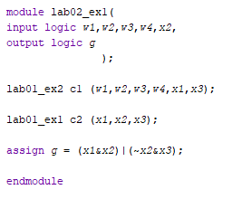
--
Lab 2 Design Source:

--
Lab 2 Constraint File:

--
Lab 2 Wave Diagram:
 --
--
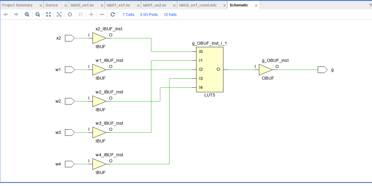
Lab 2 Schematic:
--
Post-lab Questions:
1. In Vivado, examine the RTL schematic. Include a screenshot of the output in your report. How does it compare to your design and implementation? What, if any, differences exist? Why?
2. Examine the compilation report (Synthesis Report). Include a screenshot in your report. How many logic elements does your design require? How does this compare with the RTL viewer (Schematic)? Does this make sense? Why or why not?
---
Please answer the above questions based on the given information, and go into detail so that I may fully understand the concept(s) that are confusing methank you.
module lab01_ex1( input logic x1,x2,x3, output logic F); assign F=(x1_x2)(x2sx3); endmodule nodule lab01_ex2( input logic w1,w2,w3,w4, output logic x1,x3 assign x1=(w1 sw 2)(w3&w4); assign x3=(w1&w3)(w2w4); endmodule module lab02_ex1( input logic 1,v2,v3,v4,x2, output logic g lab01_ex2 c1 (v1,v2,v3,v4,x1,x3); lab01_ex1 c2 (x1,x2,x3); assign g=(x1sx2)(x2sx3); endmodule Design Sources (1) \[ \begin{array}{l} \text { \#lab02_ex1 (lab02_ex1.sv) (2) } \\ \text { c1: lab01_ex2 (lab01_ex2.sv) } \\ \text { c2 : lab01_ex1 (lab01_ex1.sv) } \end{array} \] Constraints module lab01_ex1( input logic x1,x2,x3, output logic F); assign F=(x1_x2)(x2sx3); endmodule nodule lab01_ex2( input logic w1,w2,w3,w4, output logic x1,x3 assign x1=(w1 sw 2)(w3&w4); assign x3=(w1&w3)(w2w4); endmodule module lab02_ex1( input logic 1,v2,v3,v4,x2, output logic g lab01_ex2 c1 (v1,v2,v3,v4,x1,x3); lab01_ex1 c2 (x1,x2,x3); assign g=(x1sx2)(x2sx3); endmodule Design Sources (1) \[ \begin{array}{l} \text { \#lab02_ex1 (lab02_ex1.sv) (2) } \\ \text { c1: lab01_ex2 (lab01_ex2.sv) } \\ \text { c2 : lab01_ex1 (lab01_ex1.sv) } \end{array} \] Constraints
Step by Step Solution
There are 3 Steps involved in it
Step: 1

Get Instant Access to Expert-Tailored Solutions
See step-by-step solutions with expert insights and AI powered tools for academic success
Step: 2

Step: 3

Ace Your Homework with AI
Get the answers you need in no time with our AI-driven, step-by-step assistance
Get Started


