

Question: Hook A Arm Cable V=0.15 m/s 5000kg 1m Pulley 2.0m Gear box A-Frame Shaft Coupling Motor Speed: 1500 rpm Power: 3 kW D B
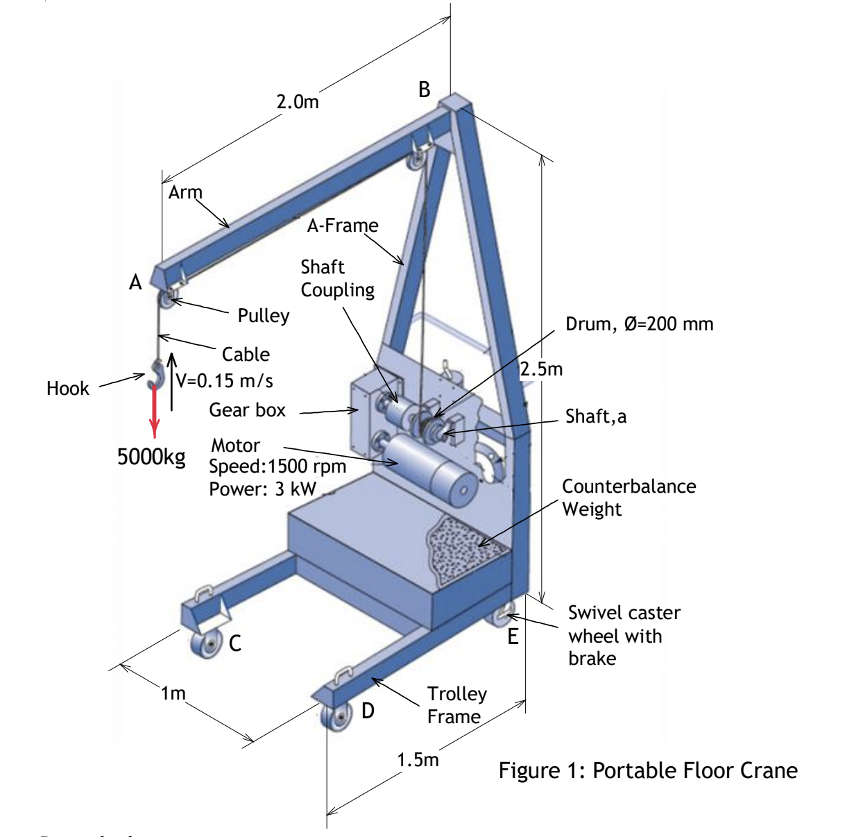
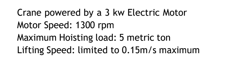
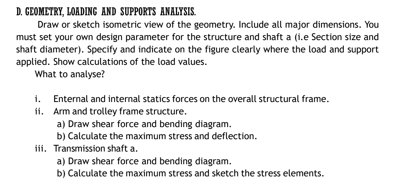
Hook A Arm Cable V=0.15 m/s 5000kg 1m Pulley 2.0m Gear box A-Frame Shaft Coupling Motor Speed: 1500 rpm Power: 3 kW D B Trolley Frame 1.5m 2.5m E Drum, -200 mm Shaft, a Counterbalance Weight Swivel caster wheel with brake Figure 1: Portable Floor Crane Crane powered by a 3 kw Electric Motor Motor Speed: 1300 rpm Maximum Hoisting load: 5 metric ton Lifting Speed: limited to 0.15m/s maximum D. GEOMETRY, LOADING AND SUPPORTS ANALYSIS. Draw or sketch isometric view of the geometry. Include all major dimensions. You must set your own design parameter for the structure and shaft a (i.e Section size and shaft diameter). Specify and indicate on the figure clearly where the load and support applied. Show calculations of the load values. What to analyse? i. Enternal and internal statics forces on the overall structural frame. Arm and trolley frame structure. ii. a) Draw shear force and bending diagram. b) Calculate the maximum stress and deflection. iii. Transmission shaft a. a) Draw shear force and bending diagram. b) Calculate the maximum stress and sketch the stress elements.
Step by Step Solution
There are 3 Steps involved in it
It appears that youre asking for a detailed structural analysis of a portable floor crane This type of analysis is quite extensive and would require s... View full answer

Get step-by-step solutions from verified subject matter experts