

Question: How do I solve this? 1. R X N Y C=luf Z figure 4 In your laboratory kit you find an unlabeled inductor. Let R
How do I solve this?
1.
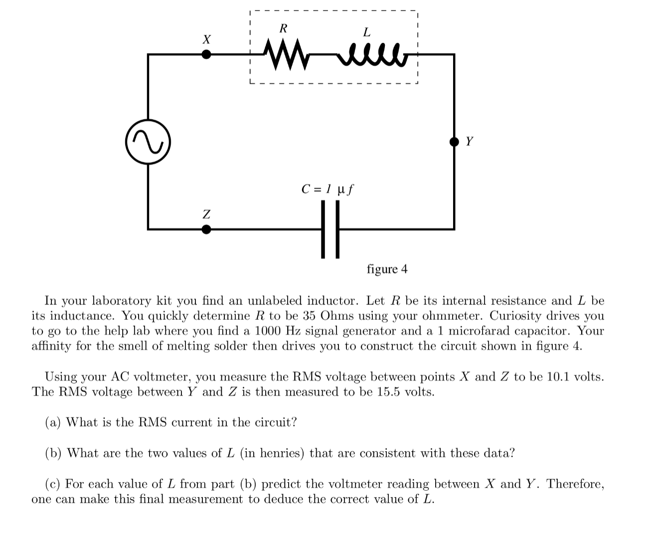
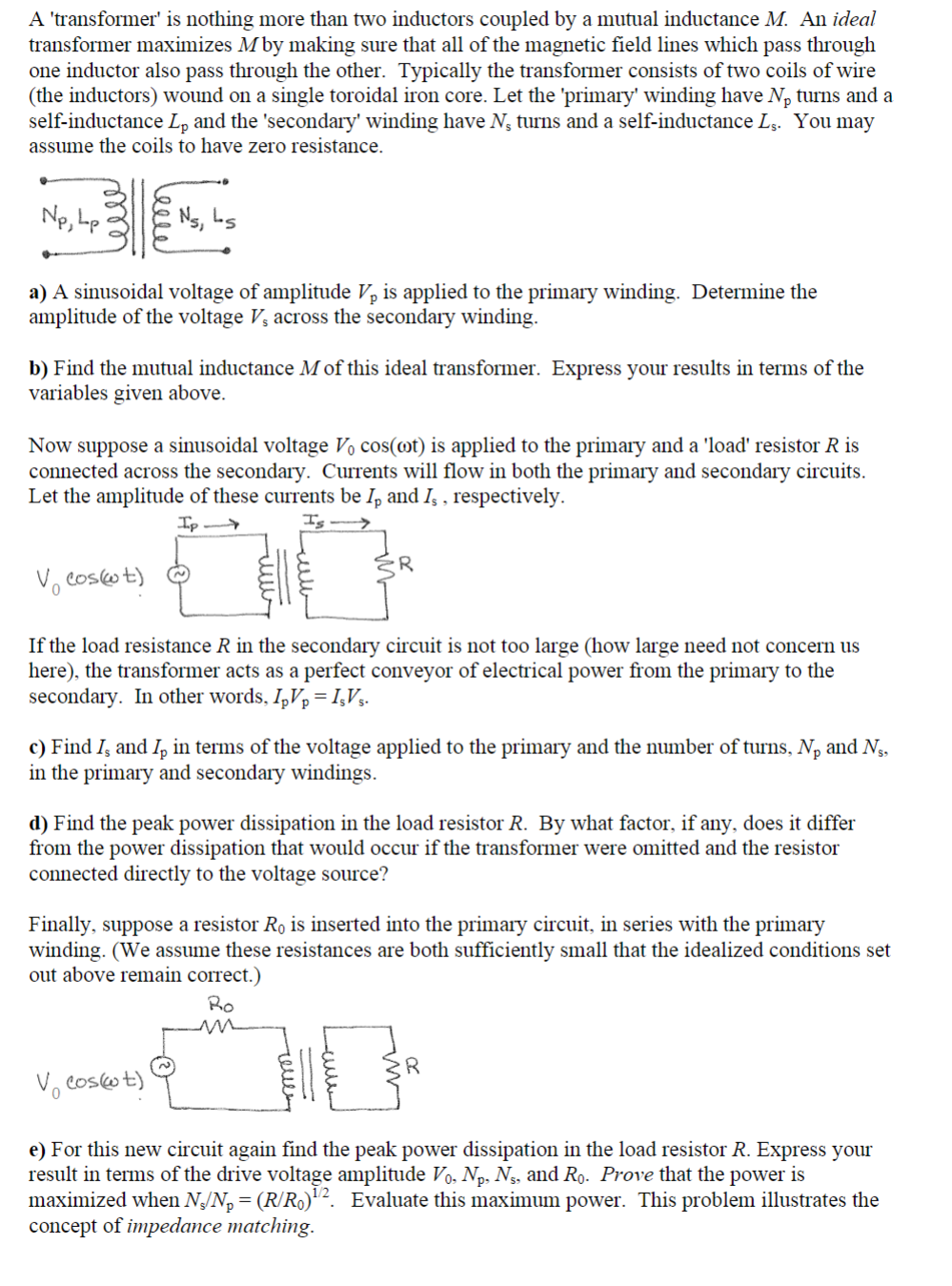
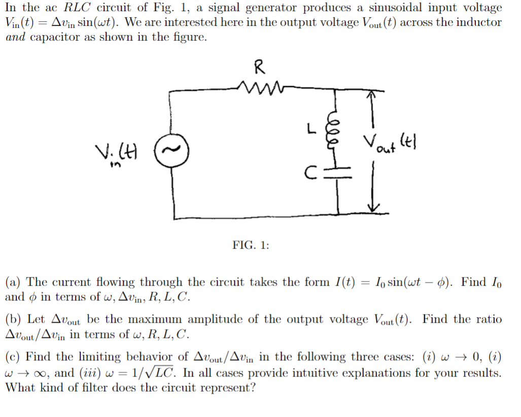
R X N Y C=luf Z figure 4 In your laboratory kit you find an unlabeled inductor. Let R be its internal resistance and L be its inductance. You quickly determine R to be 35 Ohms using your ohmmeter. Curiosity drives you to go to the help lab where you find a 1000 Hz signal generator and a 1 microfarad capacitor. Your affinity for the smell of melting solder then drives you to construct the circuit shown in figure 4. Using your AC voltmeter, you measure the RMS voltage between points X and Z to be 10.1 volts. The RMS voltage between Y and Z is then measured to be 15.5 volts. (a) What is the RMS current in the circuit? (b) What are the two values of L (in henries) that are consistent with these data? (c) For each value of L from part (b) predict the voltmeter reading between X and Y. Therefore, one can make this final measurement to deduce the correct value of L.A 'transformer' is nothing more than two inductors coupled by a mutual inductance M An ideal transformer maximizes M by making sure that all of the magnetic eld lines which pass through one inductor also pass through the other. Typically the transformer consists of two coils of wire (the inductors) wound on a single toroidal iron core. Let the 'prirnary\" winding have Np turns and a self-inductance L], and the 'secondary' winding have N; turns and a self-inductance I... You may assume the coils to have zero resistance. NP, L N5) L5 [4' a) A sinusoidal voltage of amplitude VP is applied to the primary winding. Determine the amplitude of the voltage V; across the secondary winding. [1) Find the mutual inductance M of this ideal transformer. Express your results in terms of the variables given above. Now suppose a sinusoidal voltage V0 cos(mt) is applied to the primary and a 'load' resistor R is connected across the secondary. Currents will flow in both the primary and secondary circuits. Let the amplitude of these currents be l\"p and I, . respectively. IpJr "Iss- v0 costs: in) ii R If the load resistance R in the secondary circuit is not too large (how large need not concern us here). the transformer acts as a perfect conveyor of electrical power from the primary to the secondary. In other words, 1pr = IsV, c) Find 1,; and [P in terms of the voltage applied to the primary and the number of turns. N9 and N5. in the primary and secondary windings. d) Find the peak power dissipation in the load resistor R. By what factor. if any. does it differ from the power dissipation that would occur if the transformer were omitted and the resistor connected directly to the voltage source? Finally, suppose a resistor R0 is inserted into the primary circuit. in series with the primary winding. (We assume these resistances are both sufciently small that the idealized conditions set out above remain correct.) 31:: new ii R e) For this new circuit again nd the peak power dissipation in the load resistor R. Express your result in terms of the drive voltage amplitude V0, Np, N5, and R0. Prove that the power is maximized when MINI, = (R/Rgf'l. Evaluate this maximum power. This problem illustrates the concept of impedance matching. In the ac RIC circuit of Fig. 1, a signal generator produces a sinusoidal input voltage Vin(t) = Avin sin(wt). We are interested here in the output voltage Vout(t) across the inductor and capacitor as shown in the figure. R L V. (H Yout (1 in C FIG. 1: (a) The current flowing through the circuit takes the form I(t) = lo sin(wt - o). Find Io and o in terms of w, Avin, R, L, C. (b) Let About be the maximum amplitude of the output voltage Vout (t). Find the ratio Avout/ Avin in terms of w, R, L, C. (c) Find the limiting behavior of About/Avin in the following three cases: (i) w - 0, (i) w -+ oo, and (iii) w = 1/VLC. In all cases provide intuitive explanations for your results. What kind of filter does the circuit represent
Step by Step Solution
There are 3 Steps involved in it

Get step-by-step solutions from verified subject matter experts