Answered step by step
Verified Expert Solution
Question
1 Approved Answer
Figure 1 shows a power system which is connected to a 275 kV grid source. The 275 kV voltage is step down to 132


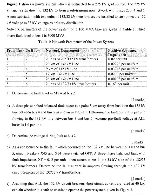
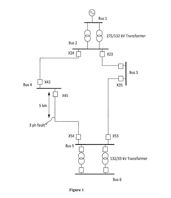
Figure 1 shows a power system which is connected to a 275 kV grid source. The 275 kV voltage is step down to 132 kV to form a sub-transmission network with buses 2, 3, 4 and 5. A new substation with two units of 132/33 kV transformers are installed to step down the 132 kV voltage to 33 kV voltage as primary distribution. Network parameters of the power system on a 100 MVA base are given in Table 1. Three phase fault level at bus 1 is 3000 MVA. Table 1: Network Parameters of the Power System From Bus To Bus 1 2 2 3 4 5 2 3 4 5 5 6 Network Component 2 units of 275/132 kV transformers 20 km of 132 kV Line 9 km of 132 kV Line 17 km 132 kV Line 26 km of 132 kV Line 2 units of 132/33 kV transformers a) Determine the fault level in MVA at bus 2. Positive Sequence Impedance 0.02 per unit 0.02278 per unit/km 0.03743 per unit/km 0.0203 per unit/km 0.00108 per unit/km 0.163 per unit [5 marks] b) A three phase bolted balanced fault occur at a point 5 km away from bus 4 on the 132 kV line between bus 4 and bus 5 as shown in Figure 1. Determine the fault current in per unit flowing in the 132 kV line between bus 3 and bus 5. Assume pre-fault voltage at ALL buses is 1.0 per unit. c) Determine the voltage during fault at bus 2. [3 marks] d) As a consequence to the fault which occurred on the 132 kV line between bus 4 and bus 5, circuit breakers X45 and X54 were switched OFF. A three-phase balanced fault with fault impedance, XF = 0.2 per unit then occurs at bus 6, the 33 kV side of the 132/33 kV transformers. Determine the fault current in amperes flowing through the 132 kV circuit breakers of the 132/33 kV transformers. [6 marks] [7 marks] e) Assuming that ALL the 132 kV circuit breakers short circuit current are rated at 40 kA, explain whether it is safe or unsafe to operate the power system given in Figure 1. Bus 4 X42 5 km 3 ph fault Bus 2 X24 X45 X54 Bus 5 Figure 1 Bus 1 275/132 kV Transformer X23 X35 X53 Bus 3 132/33 kV Transformer Bus 6
Step by Step Solution
★★★★★
3.47 Rating (167 Votes )
There are 3 Steps involved in it
Step: 1
Answer to question a To determine the fault level in MVA at bus 2we can use the following equation Fault level at bus 2 Fault level at bus 1 1 Impedance between bus 1 and bus 2 Step 1 Calculate the im...
Get Instant Access to Expert-Tailored Solutions
See step-by-step solutions with expert insights and AI powered tools for academic success
Step: 2

Step: 3

Ace Your Homework with AI
Get the answers you need in no time with our AI-driven, step-by-step assistance
Get Started


