Question: https://www.arduino.cc/ Show me the Arduino Code, make good comments that clearly identify each task use #193 as the last 3 digits of my student I.D
https://www.arduino.cc/
Show me the Arduino Code, make good comments that clearly identify each task
use #193 as the last 3 digits of my student I.D


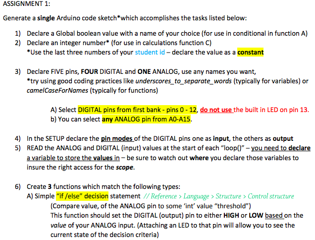
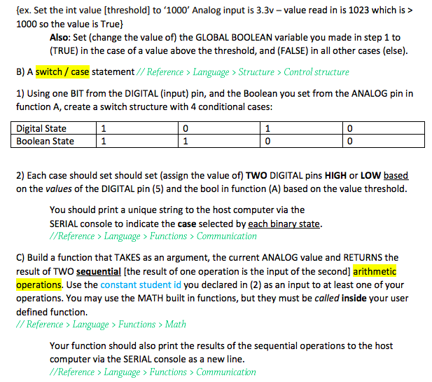
ASSIGNMENT 1: Generate a single Arduino code sketch*which accomplishes the tasks listed below: 1) 2) Declare a Global boolean value with a name of your choice (for use in conditional in function A) Declare an integer number* (for use in calculations function C) *Use the last three numbers of your student id - declare the value as a constant 3) Declare FIVE pins, FOUR DIGITAL and ONE ANALOG, use any names you want, *try using good coding practices like underscores to_separate_words (typically for variables) or camelCaseForNames (typically for functions) b) You can select any ANALOG pin from AO-A1s 4) In the SETUP declare the pin modes of the DIGITAL pins one as input, the others as output 5) READ the ANALOG and DIGITAL (input) values at the start of each "loop" -you need to declare a variable to store the values in- be sure to watch out where you declare those variables to insure the right access for the scope. 6) Create 3 functions which match the following types A) Simple "if /else" decision statement //Reference > Language> Structure > Control structure (Compare value, of the ANALOG pin to some 'int' value "threshold") This function should set the DIGITAL (output) pin to either HIGH or LOW based on the value of your ANALOG input. (Attaching an LED to that pin will allow you to see the current state of the decision criteria) ex. Set the int value [threshold] to 1000' Analog input is 3.3v- value read in is 1023 which is > 1000 so the value is True) Also: Set (change the value of) the GLOBAL BOOLEAN variable you made in step 1 to (TRUE) in the case of a value above the threshold, and (FALSE) in all other cases (else) B) A switch/ case statement/ /Reference> Language > Structure>Control structure 1) Using one BIT from the DIGITAL (input) pin, and the Boolean you set from the ANALOG pin in function A, create a switch structure with 4 conditional cases: Digital State Boolean State 0 0 0 0 2) Each case should set should set (assign the value of) TWO DIGITAL pins HIGH or LOW based on the values of the DIGITAL pin (5) and the bool in function (A) based on the value threshold You should print a unique string to the host computer via the SERIAL console to indicate the case selected by each binary state //Reference> Language> Functions> Communication C) Build a function that TAKES as an argument, the current ANALOG value and RETURNS the result of TWO sequential [the result of one operation is the input of the second arithmetic operations. Use the constant student id you declared in (2) as an input to at least one of your operations. You may use the MATH built in functions, but they must be called inside your user defined function // Reference >Language > Functions Math Your function should also print the results of the sequential operations to the host computer via the SERIAL console as a new line //Reference > Language > Functions > Communication Questions How much total memory will your compiled sketch need once uploaded to the microcontroller? Hint-this is given when you successfully compile your code-a screenshot would be a great response here! How much memory (and what type of memory) are the variables in your sketch using whenin "run time on the Arduino? Hint: Add the declared size of all the non-constant declarations and refer to the table in the "in retrospect" power point (or the refrence) Using the built in timing capabilities of the ATMega chiphow could you practically time the execution of one full loop of code execution? ASSIGNMENT 1: Generate a single Arduino code sketch*which accomplishes the tasks listed below: 1) 2) Declare a Global boolean value with a name of your choice (for use in conditional in function A) Declare an integer number* (for use in calculations function C) *Use the last three numbers of your student id - declare the value as a constant 3) Declare FIVE pins, FOUR DIGITAL and ONE ANALOG, use any names you want, *try using good coding practices like underscores to_separate_words (typically for variables) or camelCaseForNames (typically for functions) b) You can select any ANALOG pin from AO-A1s 4) In the SETUP declare the pin modes of the DIGITAL pins one as input, the others as output 5) READ the ANALOG and DIGITAL (input) values at the start of each "loop" -you need to declare a variable to store the values in- be sure to watch out where you declare those variables to insure the right access for the scope. 6) Create 3 functions which match the following types A) Simple "if /else" decision statement //Reference > Language> Structure > Control structure (Compare value, of the ANALOG pin to some 'int' value "threshold") This function should set the DIGITAL (output) pin to either HIGH or LOW based on the value of your ANALOG input. (Attaching an LED to that pin will allow you to see the current state of the decision criteria) ex. Set the int value [threshold] to 1000' Analog input is 3.3v- value read in is 1023 which is > 1000 so the value is True) Also: Set (change the value of) the GLOBAL BOOLEAN variable you made in step 1 to (TRUE) in the case of a value above the threshold, and (FALSE) in all other cases (else) B) A switch/ case statement/ /Reference> Language > Structure>Control structure 1) Using one BIT from the DIGITAL (input) pin, and the Boolean you set from the ANALOG pin in function A, create a switch structure with 4 conditional cases: Digital State Boolean State 0 0 0 0 2) Each case should set should set (assign the value of) TWO DIGITAL pins HIGH or LOW based on the values of the DIGITAL pin (5) and the bool in function (A) based on the value threshold You should print a unique string to the host computer via the SERIAL console to indicate the case selected by each binary state //Reference> Language> Functions> Communication C) Build a function that TAKES as an argument, the current ANALOG value and RETURNS the result of TWO sequential [the result of one operation is the input of the second arithmetic operations. Use the constant student id you declared in (2) as an input to at least one of your operations. You may use the MATH built in functions, but they must be called inside your user defined function // Reference >Language > Functions Math Your function should also print the results of the sequential operations to the host computer via the SERIAL console as a new line //Reference > Language > Functions > Communication Questions How much total memory will your compiled sketch need once uploaded to the microcontroller? Hint-this is given when you successfully compile your code-a screenshot would be a great response here! How much memory (and what type of memory) are the variables in your sketch using whenin "run time on the Arduino? Hint: Add the declared size of all the non-constant declarations and refer to the table in the "in retrospect" power point (or the refrence) Using the built in timing capabilities of the ATMega chiphow could you practically time the execution of one full loop of code execution
Step by Step Solution
There are 3 Steps involved in it

Get step-by-step solutions from verified subject matter experts


