Answered step by step
Verified Expert Solution
Question
1 Approved Answer
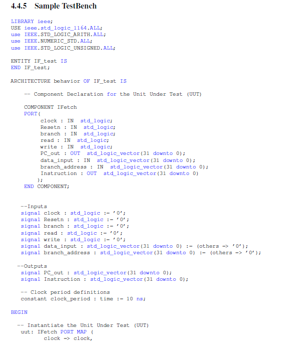
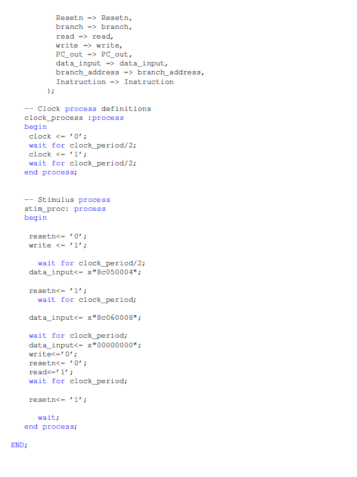
I already converted the values into hexadecimal, I just need this code to be translated to VHDL, so I can add it to the testbench.
I already converted the values into hexadecimal, I just need this code to be translated to VHDL, so I can add it to the testbench. My id is 8893 and the vowel is i. The oher two images below is the testbech
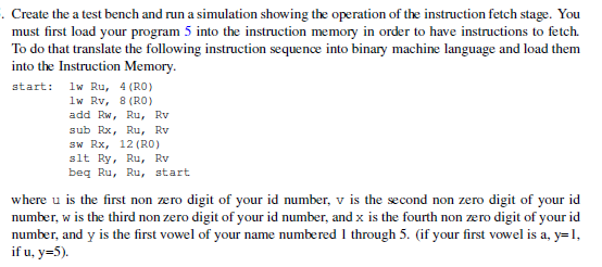
Create the a test bench and run a simulation showing the operation of the instruction fetch stage. You must first load your program 5 To do that translate the following instruction sequence into binary machine language and load them into the Instruction Memory start: w Ru, 4 (RO) into the instruction memory in order to have instructions to fetch. o lw Rv, 8 (RO) add Rw, Ru, Rv sub Rx, Ru, Rv sw Rx, 12 (RO) slt Ry,Ru, Rv beq Ru, Ru, start where u is the first non zero digit of your id number, v is the second non zero digit of your id number, w is the third non zero digit of your id number, and x is the fourth non zero digit of your id number, and y is the first vowel of your name numbered 1 through 5. (if your first vowel is a, y-1 if u. y-5). 4.4.5 Sample TestBench LIBRARY ieee: USE ieee.std logic_1164.ALL use IEEE.STD_LOGIC ARITH.ALL use IEEE. NUMERIC STD. ALL; use IEEE. STD_LOGIC_UNSIGNED. ALL ENTITY IF test IS END IF_test: ARCHITECTURE behavior OF IF test IS Component Declaration for the Unit Under Test (UUT) COMPONENT IFetch PORT clock IN std logic Resetn : IN std_logic; branch: IN std_logic; read IN std logic write: IN std logic; PC_ out : OUT std_logic_vector (31 downto 0); data input : IN std logic vector (31 downto 0) branch addressIN std_logic vector (31 downto 0) Instruction OUT std_logic_vector (31 downto 0) END COMPONENT Inputs signal clock : std 1ogic:-'0 signal Resetn: stdlogic :-0 signal branch: stdlogic :-0 signal read: std logic:-0 signal write : std 1ogic:-'0 signal data_input: std logicvector (31 downto 0) :-(others0) signal branch_address std logic vector (31 downto 0) -(others0') Outputs signal PC_out : std logic_vector (31 downto 0) signal Instruction std_logic vector (31 downto 0) Clock period definitions constant clock period: time :- 10 ns; BEGIN Instantiate the Unit Under Test (UUT) uut IFetch PORT MAP clock->clock, Resetn-Resetn, branch-> branch, read-> read, write->write, PC out-> PC out, data input-> data input, branch address->branch_address, Instruction-Instruction - Clock process definitions clock process :process begin clock -0 wait for clock period/2; clockStep by Step Solution
There are 3 Steps involved in it
Step: 1
Get Instant Access to Expert-Tailored Solutions
See step-by-step solutions with expert insights and AI powered tools for academic success
Step: 2
Step: 3
Ace Your Homework with AI
Get the answers you need in no time with our AI-driven, step-by-step assistance
Get Started