I dont understand how to write a program that when using a 3-dip switch connected to the Arduino. Make a program that is like sequential tail lights.
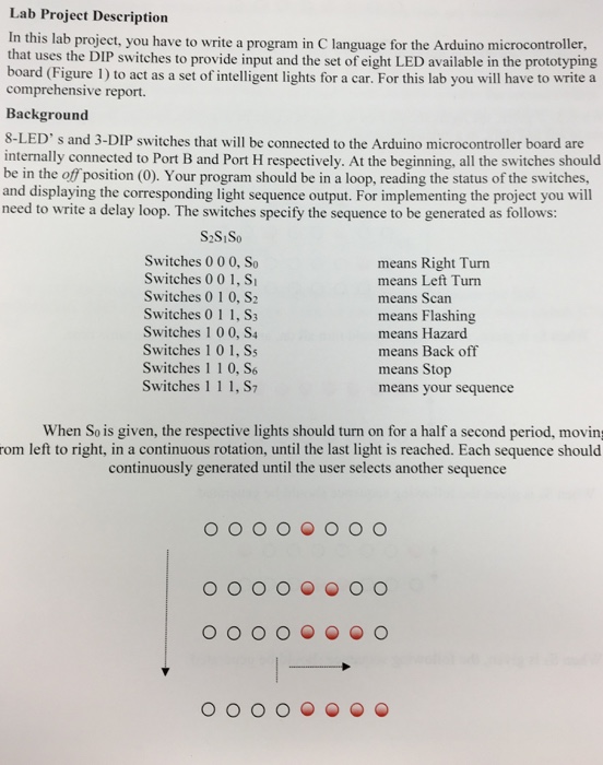
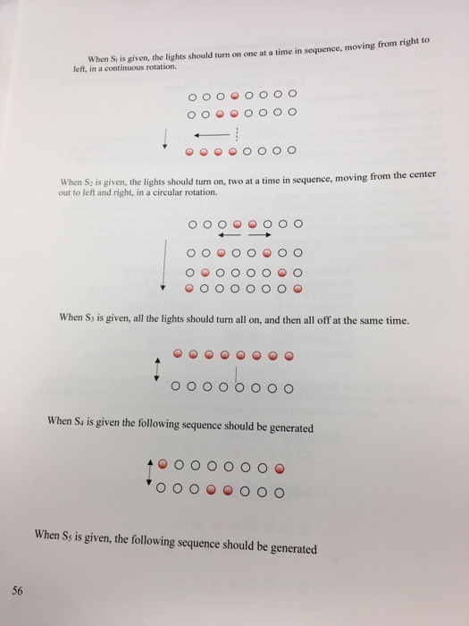
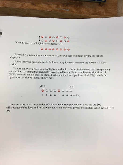
Lab Project Description In this lab project, you have to write a program in C language for the Arduino microcontroller, that uses the DIP switches to provide input and the set of eight LED available in the prototyping board (Figure 1) to act as a set of intelligent lights for a car. For this lab you will have to write a comprehensive report Background 8-LED' s and 3-DIP switches that will be connected to the Arduino microcontroller board are internally connected to Port B and Port H respectively. At the beginning, all the switches should be in the off position (0). Your program should be in a loop, reading the status of the switches, and displaying the corresponding light sequence output. For implementing the project you will need to write a delay loop. The switches specify the sequence to be generated as follows: S2SiSo Switches 000, So Switches 00 1,S Switches 010, S2 Switches 011, S Switches 1 0 0, S Switches 1 0 1, Ss Switches 1 1 0, S6 Switches 11 1, S7 means Right Turn means Left Turn means Scan means Flashing means Hazard means Back off means Stop means your sequence When So is given, the respective lights should turn on for a half a second period, moving rom left to right, in a continuous rotation, until the last light is reached. Each sequence should continuously generated until the user selects another sequence Lab Project Description In this lab project, you have to write a program in C language for the Arduino microcontroller, that uses the DIP switches to provide input and the set of eight LED available in the prototyping board (Figure 1) to act as a set of intelligent lights for a car. For this lab you will have to write a comprehensive report Background 8-LED' s and 3-DIP switches that will be connected to the Arduino microcontroller board are internally connected to Port B and Port H respectively. At the beginning, all the switches should be in the off position (0). Your program should be in a loop, reading the status of the switches, and displaying the corresponding light sequence output. For implementing the project you will need to write a delay loop. The switches specify the sequence to be generated as follows: S2SiSo Switches 000, So Switches 00 1,S Switches 010, S2 Switches 011, S Switches 1 0 0, S Switches 1 0 1, Ss Switches 1 1 0, S6 Switches 11 1, S7 means Right Turn means Left Turn means Scan means Flashing means Hazard means Back off means Stop means your sequence When So is given, the respective lights should turn on for a half a second period, moving rom left to right, in a continuous rotation, until the last light is reached. Each sequence should continuously generated until the user selects another sequence