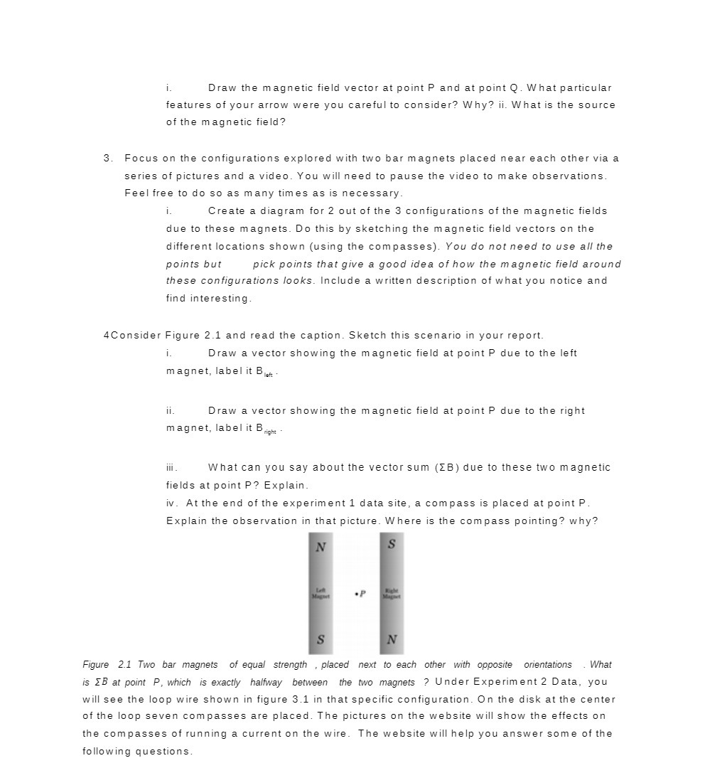
i. Draw the magnetic field vector at point P and at point Q. What particular features of your arrow were you careful to consider? Why? ii. What is the source of the magnetic field? 3. Focus on the configurations explored with two bar magnets placed near each other via a series of pictures and a video. You will need to pause the video to make observations. Feel free to do so as many times as is necessary. i. Create a diagram for 2 out of the 3 configurations of the magnetic fields due to these magnets. Do this by sketching the magnetic field vectors on the different locations shown (using the com passes). You do not need to use all the points but pick points that give a good idea of how the magnetic field around these configurations looks. Include a written description of what you notice and find interesting. 4Consider Figure 2.1 and read the caption. Sketch this scenario in your report. i. Draw a vector showing the magnetic field at point P due to the left mag net. label it BM. ii. Draw a vector showing the magnetic field at point P due to the right magnet, label it l3,iElhl . iii. What can you say about the vector sum {EB} due to these two magnetic fields at point P? Explain. iv. At the end of the experiment 1 data site, a compass is placed at point P. Explain the observation in that picture. Where is the compass pointing? why? I orl Figure 2.1 Tm bar magnets of equal strength ,placed next to each other nirh opposite orientations .What is EB at point P, midi is exactly halvay between the Mo magnets .7 Under Experiment 2 Data, you will see the loop wire shown in figure 3.1 in that specific configuration. 0n the disk at the center of the loop seven compasses are placed. The pictures on the website will show the effects on the compasses of running a current on the wire. The website will help you answer some of the following questions