

Answered step by step
Verified Expert Solution
Question
1 Approved Answer
I give part 1 to you and thise is part 2 about datastructer proj please help me to solve it ! And i want to
I give part to you and thise is part about datastructer proj please help me to solve it
And i want to give i another page the last part
In this
Clocking the register file
The register file that you created in the first part was a combinational circuit. This causes some serious problems if for example, address and address are the same. The circuit would read output from the location referenced by address at the same time that the input is overwriting that of
These problems can be solved by synchronising the register file to a clock. You will need to add an extra input named clock, and give the register file the following behaviour:
On the rising edge of the clock:
Output produces the item within the register file that is address by Address
Input is used to supply a value that is written into the location addressed by Address
Under all other circumstances
the outputs are held constant at the values they assumed during the last rising edge of the clock. You should check your design thoroughly, and in particular make sure that it behaves sensibly when the address for the input is the gam address of ofe of the outp
Enabling the register file
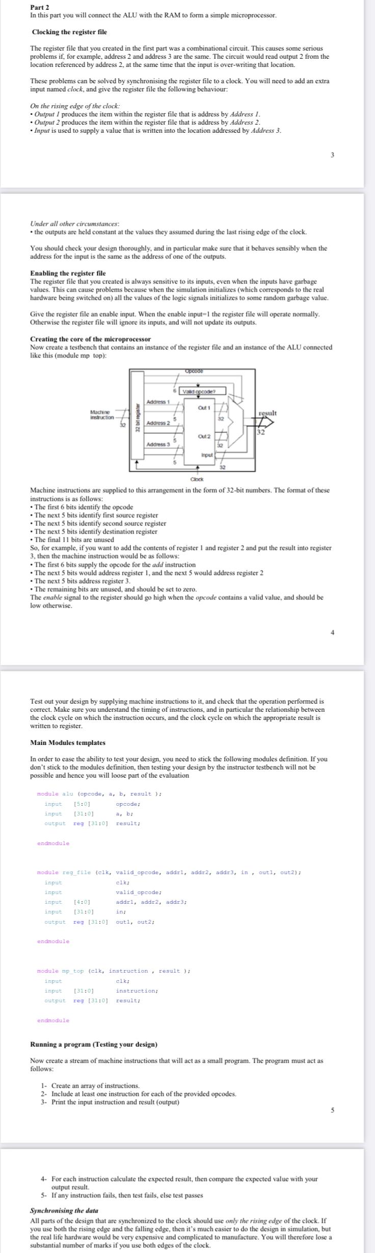
The register file that you created is always sensitive to its inputs, even when the inputs have garbage values. This can case poble values. This can cause problems because when the simulation initializes which corresponds to the real hardware being switched on all the values of the logic signals initializes to some random garbage value. Give the register file an enable input. When the enable input the register file will operate normally. Otherwise the register file will ignore its inputs, and will not update its outputs. Creating the core of the microprocessor like this module mp top:
Test out your design by supplying machine instructions to it and check that the operation performed is correct. Make sure you understand the timing of instructions, and in particular the relationship between the clock cycle on which the instruction occurs, and the clock cycle on which the appropriate result is the clock cycle on w
Main Modules templates
In order to ease the ability to test your design, you need to stick the following modules definition. If you don't stick to the modules definition, then testing your des
Machine instructions are
instructions is as follows: The first bits identify the opcode
The next bits identify first source register
The next bits identify destination register
The final bits are unused
So for example, if you want to add the contents of register and register and put the result into register
The first bits supply the opcode for the as follows:
The next bits would address register and the next would address register The next bits address register
The remaining bits are unused, and should be set to zero.
low otherwise.
endmodule
hodule regfile clk validopcode, addr addr addr in outl, out; input clk;
: addr addr addr;
re
:
out out;
Running a program Testing your design
Now create a stream of machine instructions that will act as a small program. The program must act as
fllows:
Create an array of instructions.
Include at least one instruction for each of the provided opcodes.
instruction and result output
For each instruction calculate the expected result, then compare the expected value with your
If any instruction fails, then test fails, else test passes
Synchronising the data
All parts of the design that are synchronized to the clock should use only the rising edge of the clock. If you use both the rising edge and the falling edge, then it's much easier to do the design in simulation, but the real life hardware would be very expensive and complicated substantial number of marks if you use both edges of the clock.
Step by Step Solution
There are 3 Steps involved in it
Step: 1

Get Instant Access to Expert-Tailored Solutions
See step-by-step solutions with expert insights and AI powered tools for academic success
Step: 2

Step: 3
Ace Your Homework with AI
Get the answers you need in no time with our AI-driven, step-by-step assistance
Get Started
How To Make A Database In Historical Studies
Authors: Tiago Luis Gil
1st Edition
3030782409, 978-3030782405