

Question
I just need Block diagram of top-level structure. Showing all modules with types and instance names Signal names Port names and A table describing the
I just need Block diagram of top-level structure. Showing all modules with types and instance names Signal names Port names
and A table describing the testing carried out
I just need Block diagram of top-level structure. Showing all modules with types and instance names Signal names Port names
and A table describing the testing carried out.
I cannot upload my VHDL code here so could you please base on this information to make the block diagram and a describing table for me. Thank you
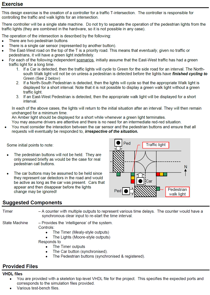
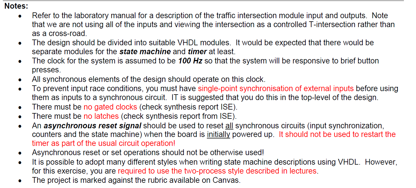
Exercise This design exercise is the creation of a controller for a traffic T-intersection. The controller is responsible for controlling the traffic and walk lights for an intersection. There controller will be a single state machine. Do not try to separate the operation of the pedestrian lights from the traffic lights (they are combined in the hardware, so it is not possible in any case). The operation of the intersection is described by the following: There are two pedestrian buttons There is a single car sensor (represented by another button). The East-West road on the top of the T is a priority road. This means that eventually, given no traffic or pedestrians, it it will I have a green light indefinitely. For each of the following independent scenarios, initially assume that the East-West traffic has had a green traffic light for a long time. 1. If a Car is detected, then the traffic lights will cycle to Green for the side road for an interval. The North- south Walk light will not be on unless a pedestrian is detected before the lights have finished cycling to Green (See 2 below) If a North-South Pedestrian is detected, then the lights will cycle so that the appropriate Walk light is displayed for a short interval. Note that it is not possible to display a green walk light without a green traffic light 3. If an East-West Pedestrian is detected, then the appropriate walk light will be displayed for a short interval. In each of the above cases, the lights will return to the initial situation after an interval. They will then remain unchanged for a minimum time. An Amber light should be displayed for a short while whenever a green light terminates. You may assume drivers are attentive and there is no need for an intermediate red-red situation. You must consider the interaction between the car sensor and the pedestrian buttons and ensure that all requests will eventually be responded to, irrespective of the situation. 2 . Ped Some initial points to note: Traffic light The pedestrian buttons will not be held. They are only pressed briefly as would be the case for real pedestrian call buttons. The car buttons may be assumed to be held since they represent car detectors in the road and would be active as long as the car was present. Cars that appear and then disappear before the lights change may be ignored! Car Ped Pedestrian walk light Suggested Components Timer - A counter with multiple outputs to represent various time delays. The counter would have a synchronous clear input to re-start the time interval. State Machine Provides the 'intelligence of the system. Controls: The Timer (Mealy-style outputs) The Lights (Moore-style outputs) Responds to The Timer outputs The Car button (synchronised). The Pedestrian buttons (synchronised & registered) Provided Files VHDL files You are provided with a skeleton top-level VHDL file for the project. This specifies the expected ports and corresponds to the simulation files provided. Various test-bench files. Notes: Refer to the laboratory manual for a description of the traffic intersection module input and outputs. Note that we are not using all of the inputs and viewing the intersection as a controlled T-intersection rather than as a cross-road. The design should be divided into suitable VHDL modules. It would be expected that there would be separate modules for the state machine and timer at least. The clock for the system is assumed to be 100 Hz so that the system will be responsive to brief button presses. All synchronous elements of the design should operate on this clock. To prevent input race conditions, you must have single-point synchronisation of external inputs before using them as inputs to a synchronous circuit. IT is suggested that you do this in the top-level of the design. There must be no gated clocks (check synthesis report ISE). There must be no latches (check synthesis report from ISE). An asynchronous reset signal should be used to reset all synchronous circuits (input synchronization, counters and the state machine) when the board is initially powered up. It should not be used to restart the timer as part of the usual circuit operation! Asynchronous reset or set operations should not be otherwise used! It is possible to adopt many different styles when writing state machine descriptions using VHDL. However, for this exercise, you are required to use the two-process style described in lectures. The project is marked against the rubric available on Canvas. . Exercise This design exercise is the creation of a controller for a traffic T-intersection. The controller is responsible for controlling the traffic and walk lights for an intersection. There controller will be a single state machine. Do not try to separate the operation of the pedestrian lights from the traffic lights (they are combined in the hardware, so it is not possible in any case). The operation of the intersection is described by the following: There are two pedestrian buttons There is a single car sensor (represented by another button). The East-West road on the top of the T is a priority road. This means that eventually, given no traffic or pedestrians, it it will I have a green light indefinitely. For each of the following independent scenarios, initially assume that the East-West traffic has had a green traffic light for a long time. 1. If a Car is detected, then the traffic lights will cycle to Green for the side road for an interval. The North- south Walk light will not be on unless a pedestrian is detected before the lights have finished cycling to Green (See 2 below) If a North-South Pedestrian is detected, then the lights will cycle so that the appropriate Walk light is displayed for a short interval. Note that it is not possible to display a green walk light without a green traffic light 3. If an East-West Pedestrian is detected, then the appropriate walk light will be displayed for a short interval. In each of the above cases, the lights will return to the initial situation after an interval. They will then remain unchanged for a minimum time. An Amber light should be displayed for a short while whenever a green light terminates. You may assume drivers are attentive and there is no need for an intermediate red-red situation. You must consider the interaction between the car sensor and the pedestrian buttons and ensure that all requests will eventually be responded to, irrespective of the situation. 2 . Ped Some initial points to note: Traffic light The pedestrian buttons will not be held. They are only pressed briefly as would be the case for real pedestrian call buttons. The car buttons may be assumed to be held since they represent car detectors in the road and would be active as long as the car was present. Cars that appear and then disappear before the lights change may be ignored! Car Ped Pedestrian walk light Suggested Components Timer - A counter with multiple outputs to represent various time delays. The counter would have a synchronous clear input to re-start the time interval. State Machine Provides the 'intelligence of the system. Controls: The Timer (Mealy-style outputs) The Lights (Moore-style outputs) Responds to The Timer outputs The Car button (synchronised). The Pedestrian buttons (synchronised & registered) Provided Files VHDL files You are provided with a skeleton top-level VHDL file for the project. This specifies the expected ports and corresponds to the simulation files provided. Various test-bench files. Notes: Refer to the laboratory manual for a description of the traffic intersection module input and outputs. Note that we are not using all of the inputs and viewing the intersection as a controlled T-intersection rather than as a cross-road. The design should be divided into suitable VHDL modules. It would be expected that there would be separate modules for the state machine and timer at least. The clock for the system is assumed to be 100 Hz so that the system will be responsive to brief button presses. All synchronous elements of the design should operate on this clock. To prevent input race conditions, you must have single-point synchronisation of external inputs before using them as inputs to a synchronous circuit. IT is suggested that you do this in the top-level of the design. There must be no gated clocks (check synthesis report ISE). There must be no latches (check synthesis report from ISE). An asynchronous reset signal should be used to reset all synchronous circuits (input synchronization, counters and the state machine) when the board is initially powered up. It should not be used to restart the timer as part of the usual circuit operation! Asynchronous reset or set operations should not be otherwise used! It is possible to adopt many different styles when writing state machine descriptions using VHDL. However, for this exercise, you are required to use the two-process style described in lectures. The project is marked against the rubric available on CanvasStep by Step Solution
There are 3 Steps involved in it
Step: 1

Get Instant Access to Expert-Tailored Solutions
See step-by-step solutions with expert insights and AI powered tools for academic success
Step: 2

Step: 3
Ace Your Homework with AI
Get the answers you need in no time with our AI-driven, step-by-step assistance
Get Started
Financial Accounting Australia And New Zealand Edition
Authors: Jerry J. Weygandt
11th Edition
1119668654, 978-1119668657