Answered step by step
Verified Expert Solution
Question
1 Approved Answer
I just need the ALU definition table filled out,thanks a y OO CO invert Invert cry neg not neg cout add over ein pass and
I just need the ALU definition table filled out,thanks 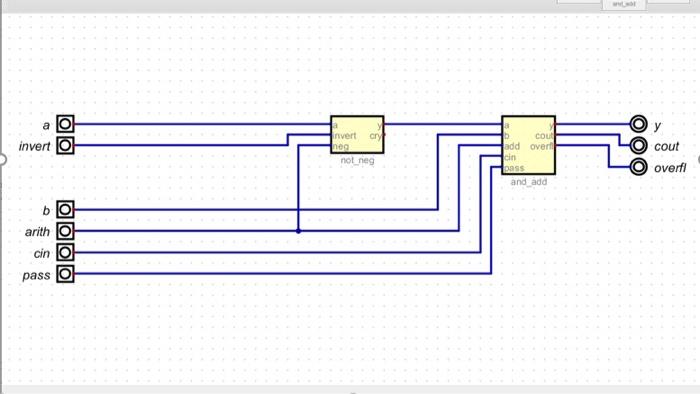
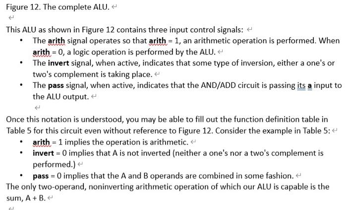
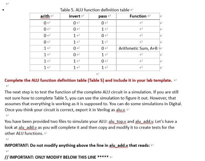
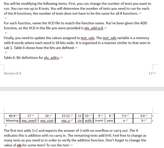
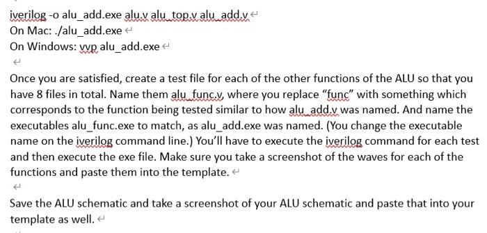
a y OO CO invert Invert cry neg not neg cout add over ein pass and add overfi b arith cin pass OOOO Figure 12. The complete ALU. This ALU as shown in Figure 12 contains three input control signals: The arith signal operates so that arith = 1, an arithmetic operation is performed. When arith = 0, a logic operation is performed by the ALU. + The invert signal, when active, indicates that some type of inversion, either a one's or two's complement is taking place. The pass signal, when active, indicates that the AND/ADD circuit is passing its a input to the ALU output. Once this notation is understood, you may be able to fill out the function definition table in Table 5 for this circuit even without reference to Figure 12. Consider the example in Table 5: arith = 1 implies the operation is arithmetic. invert = 0 implies that A is not inverted (neither a one's nor a two's complement is performed.) pass = 0 implies that the A and B operands are combined in some fashion. The only two-operand, noninverting arithmetic operation of which our ALU is capable is the sum, A+B. WAAR arithe 0 0 Table 5. ALU function definition table inverte pass Function 0 0 0 le 1e 0 1 12 e 0 Arithmetic Sum, A+B 12 0 0 12 le 12 0 0 12 0 16 1e 1e Complete the ALU function definition table (Table 5) and include it in your lab template. The next step is to test the function of the complete ALU circuit in a simulation. If you are still not sure how to complete Table 5, you can use the simulation to figure it out. However, that assumes that everything is working as it is supposed to. You can do some simulations in Digital. Once you think your circuit is correct, export it in Verilog as alu.. You have been provided two files to simulate your ALU: alu_top. and alu add.v. Let's have a look at alu add.v as you will complete it and then copy and modify it to create tests for the other ALU functions. IMPORTANT: Do not modify anything above the line in alu add.v that reads: // IMPORTANT: ONLY MODIFY BELOW THIS LINE You will be modifying the following items. First, you can change the number of tests you want to run. You can run up to 8 tests. You will determine the number of tests you need to run for each of the 8 functions; the number of tests does not have to be the same for all 8 functions. For each function, name the VCD file to match the function name. You've been given the ADD function, so the VCD in the file you were provided is alu addycd. Finally, you need to update the values assigned to test vals. The test vals variable is a memory with 8 words where each word is 18 bits wide. It is organized in a manner similar to that seen in Lab 1. Table 6 shows how the bits are defined. Table 6: Bit definitions for alu add.y. Version 0.4 17 16 7:4 3:0 Bit # 17 Meaning exp..gyerf. exe cout 15:12 11 10 80 exex cin arith invert pass be The first test adds 1+2 and expects the answer of 3 with no overflow or carry out. The 4 indicates this is addition with no carry in. The remaining tests add 0+0. Feel free to change as many tests as you need to in order to verify the addition function. Don't forget to change the value of cin for some tests! To run the test: - iverilog -o alu_add.exe alu.v alu top.v alu addy On Mac: ./alu_add.exe On Windows: we alu_add.exe Once you are satisfied, create a test file for each of the other functions of the ALU so that you have 8 files in total. Name them alu func.y, where you replace "func" with something which corresponds to the function being tested similar to how alu add.v was named. And name the executables alu_func.exe to match, as alu_add.exe was named. (You change the executable name on the iverilog command line.) You'll have to execute the iverilog command for each test and then execute the exe file. Make sure you take a screenshot of the waves for each of the functions and paste them into the template. Save the ALU schematic and take a screenshot of your ALU schematic and paste that into your template as well 


Step by Step Solution
There are 3 Steps involved in it
Step: 1

Get Instant Access to Expert-Tailored Solutions
See step-by-step solutions with expert insights and AI powered tools for academic success
Step: 2

Step: 3

Ace Your Homework with AI
Get the answers you need in no time with our AI-driven, step-by-step assistance
Get Started


