I need help figuring out which parts are missing and/or need adjustments. I am trying to make the router and switches be able to ping to one another, as well as the PCs. (CISCO, IT, PACKET TRACER, NETACAD) Switch 1
Enable
Configure terminal
Hostname S1
Vlan 21
Name Faculty
Vlan 23
Name Student
Vlan 50
Name BlackHole
Vlan 88
Name Native
Vlan 99
Name Management
Exit
Interface fa0/5
Switchport mode access
Switchport access vlan 21
Interface fa0/15
Switchport mode access
Switchport access vlan 23
[ ]
Interface g0/1
Switchport mode trunk
Switch 2
Enable
Configure terminal
Hostname S2
Vlan 21
Name Faculty
Vlan 23
Name Student
Vlan 50
Name BlackHole
Vlan 88
Name Native
Vlan 99
Name Management
Exit
Interface fa0/5
Switchport mode access
Switchport access vlan 21
Interface fa0/15
Switchport mode access
Switchport access vlan 23
[ ]
Switchport mode trunk
Router 1
Enable
Configure terminal
Hostname R1
Interface s0/0/0
Clock rate 128000
Exit
Ipv6 address 172.16.1.0 255.255.255.252
Ipv6 address Fe80::1 link-local
Ipv6 unicast-routing
Router 2
Enable
Configure terminal
Hostname R2
Interface s0/0/1
Clock rate 128000
Exit
Ipv6 address 172.16.1.0 255.255.255.252
Ipv6 address Fe80::1 link-local
Ipv6 unicast-routing
Ip route 0.0.0.0 0.0.0.0 [router IP S0/0/0?]
Router 3
Enable
Configure terminal
Hostname R3
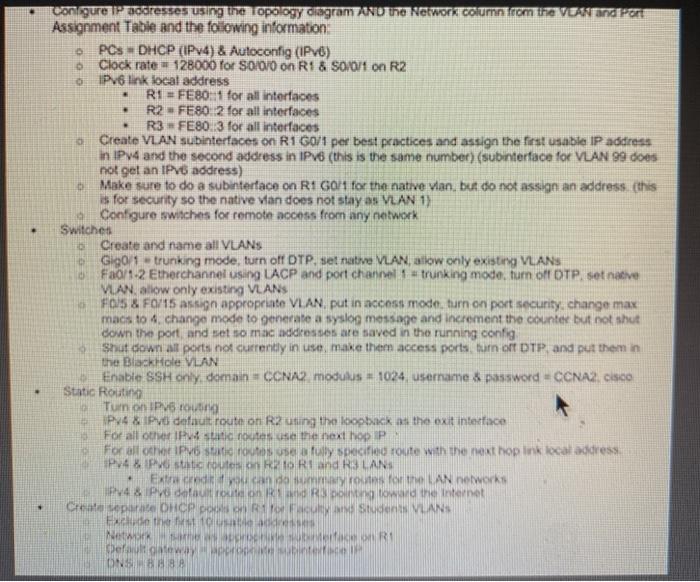
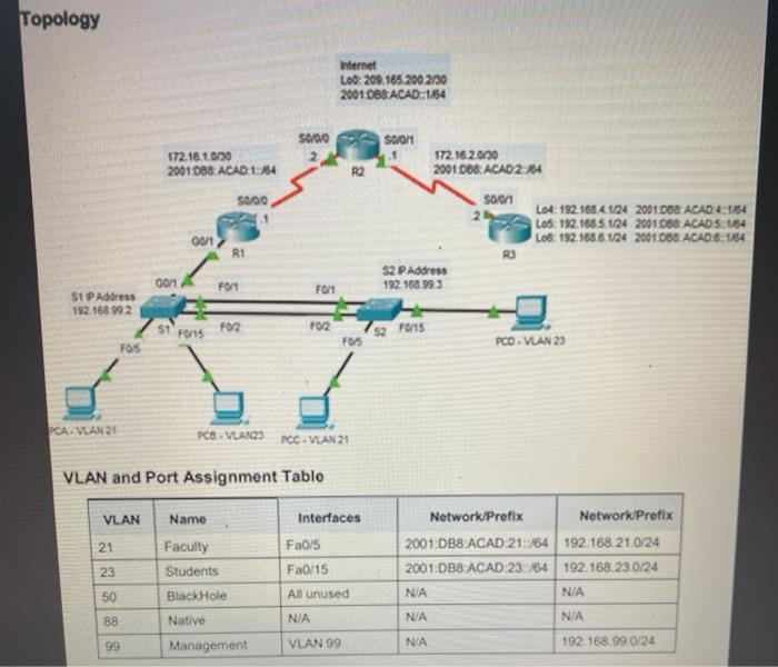
. . o con gure 2 ostesses using the opology diagram menu the Network column com the Vandrer Assignment Table and the following information PCs DHCP (IPv4) & Autoconfig (IPv6) O Clock rate 128000 Tor S0/0/0 on R1 & SO/0/1 on R2 o Pv6 link local address R1 = FE80::1 for all interfaces R2FE80: 2 for all interfaces R3 FE80.3 for all interfaces Create VLAN subinterfaces on R1 G0/1 per best practices and assign the first usable IP address in IPv4 and the second address in IPv6 (this is the same number) (subinterface for VUAN 99 does not get an IPv6 address) o Make sure to do a subinterface on R1 GO for the native vian, but do not assign an address this s for security so the native van does not stay as VLAN 1) Configure switches for remote access from any network Switches Create and name all VLANS o Gigoli trunking mode, turn off DTP. set native VLAN, allow only existing VLANS 0Fa0/1-2 Etherchannel using LACP and port channel 1 - Trunking mode, turn off OTP, set native VLAN allow only existing VLANS FOIS & F0/15 assign appropriate VLAN. put in access mode, turn on port security, change max macs to 4 change mode to generate a syslog message and increment the counter but not shut down the port and set so mac addresses are saved in the running config Shut down all ports not currently in use, make them access ports turn off DTP and put them in the Black Hole VLAN Enable SSH only domain = CCNA modulus - 1024 username & password = CCNA Cisco Static Routing Turn on IPV6-round IPV4Pv defaut route on R2 using the loopback as the exit interface For all other static notes use the next hopp For all the IPv6 sati routes ses fully specified route with the next hop link local address PV4 XP scout RRI and R3 LAN Extered oth LAN networks 4 & data Dong toward the Internet Create separate DHCP po Student VLANS Feth IN WIRD Default away WORK ONS . Topology Internet Loc: 208.165.200 2130 2001.088 ACAD:1154 S600 SOON 172.16.10/30 2001 0B8 ACADES 172.162.030 2001 068 ACAD2:24 50/00 41 500/1 2 L04: 192.168.4.124 2001 DBS ACAD 1,54 LOS: 192.168.5.124 2001068 ACAD S:154 Lob: 192.168.6.124 2001 DO ACAD:6-1154 oon RI GOM S2 P Address 192.168.99.3 Font Font S1P Address 192.168.992 1 F02 YO2 FO15 3 . FOS FOS PCO VLAN 23 PCA. VLAN 21 PCB - VAN PCC VLAN 21 VLAN and Port Assignment Table VLAN Name Interfaces 21 Faculty Students Fa0/5 Fa0/15 Network Prefix Network Prefix 2001 DB8 ACAD 21::/64192.168.21.0/24 2001:DB8 ACAD 23:54 192.168.230/24 NA N/A 23 50 Black Hole All unused 88 Native NIA NIA NIA 99 Management VLAN 99 N/A 192.168.990/24 . . o con gure 2 ostesses using the opology diagram menu the Network column com the Vandrer Assignment Table and the following information PCs DHCP (IPv4) & Autoconfig (IPv6) O Clock rate 128000 Tor S0/0/0 on R1 & SO/0/1 on R2 o Pv6 link local address R1 = FE80::1 for all interfaces R2FE80: 2 for all interfaces R3 FE80.3 for all interfaces Create VLAN subinterfaces on R1 G0/1 per best practices and assign the first usable IP address in IPv4 and the second address in IPv6 (this is the same number) (subinterface for VUAN 99 does not get an IPv6 address) o Make sure to do a subinterface on R1 GO for the native vian, but do not assign an address this s for security so the native van does not stay as VLAN 1) Configure switches for remote access from any network Switches Create and name all VLANS o Gigoli trunking mode, turn off DTP. set native VLAN, allow only existing VLANS 0Fa0/1-2 Etherchannel using LACP and port channel 1 - Trunking mode, turn off OTP, set native VLAN allow only existing VLANS FOIS & F0/15 assign appropriate VLAN. put in access mode, turn on port security, change max macs to 4 change mode to generate a syslog message and increment the counter but not shut down the port and set so mac addresses are saved in the running config Shut down all ports not currently in use, make them access ports turn off DTP and put them in the Black Hole VLAN Enable SSH only domain = CCNA modulus - 1024 username & password = CCNA Cisco Static Routing Turn on IPV6-round IPV4Pv defaut route on R2 using the loopback as the exit interface For all other static notes use the next hopp For all the IPv6 sati routes ses fully specified route with the next hop link local address PV4 XP scout RRI and R3 LAN Extered oth LAN networks 4 & data Dong toward the Internet Create separate DHCP po Student VLANS Feth IN WIRD Default away WORK ONS . Topology Internet Loc: 208.165.200 2130 2001.088 ACAD:1154 S600 SOON 172.16.10/30 2001 0B8 ACADES 172.162.030 2001 068 ACAD2:24 50/00 41 500/1 2 L04: 192.168.4.124 2001 DBS ACAD 1,54 LOS: 192.168.5.124 2001068 ACAD S:154 Lob: 192.168.6.124 2001 DO ACAD:6-1154 oon RI GOM S2 P Address 192.168.99.3 Font Font S1P Address 192.168.992 1 F02 YO2 FO15 3 . FOS FOS PCO VLAN 23 PCA. VLAN 21 PCB - VAN PCC VLAN 21 VLAN and Port Assignment Table VLAN Name Interfaces 21 Faculty Students Fa0/5 Fa0/15 Network Prefix Network Prefix 2001 DB8 ACAD 21::/64192.168.21.0/24 2001:DB8 ACAD 23:54 192.168.230/24 NA N/A 23 50 Black Hole All unused 88 Native NIA NIA NIA 99 Management VLAN 99 N/A 192.168.990/24