
I need help please. Thank you!!!
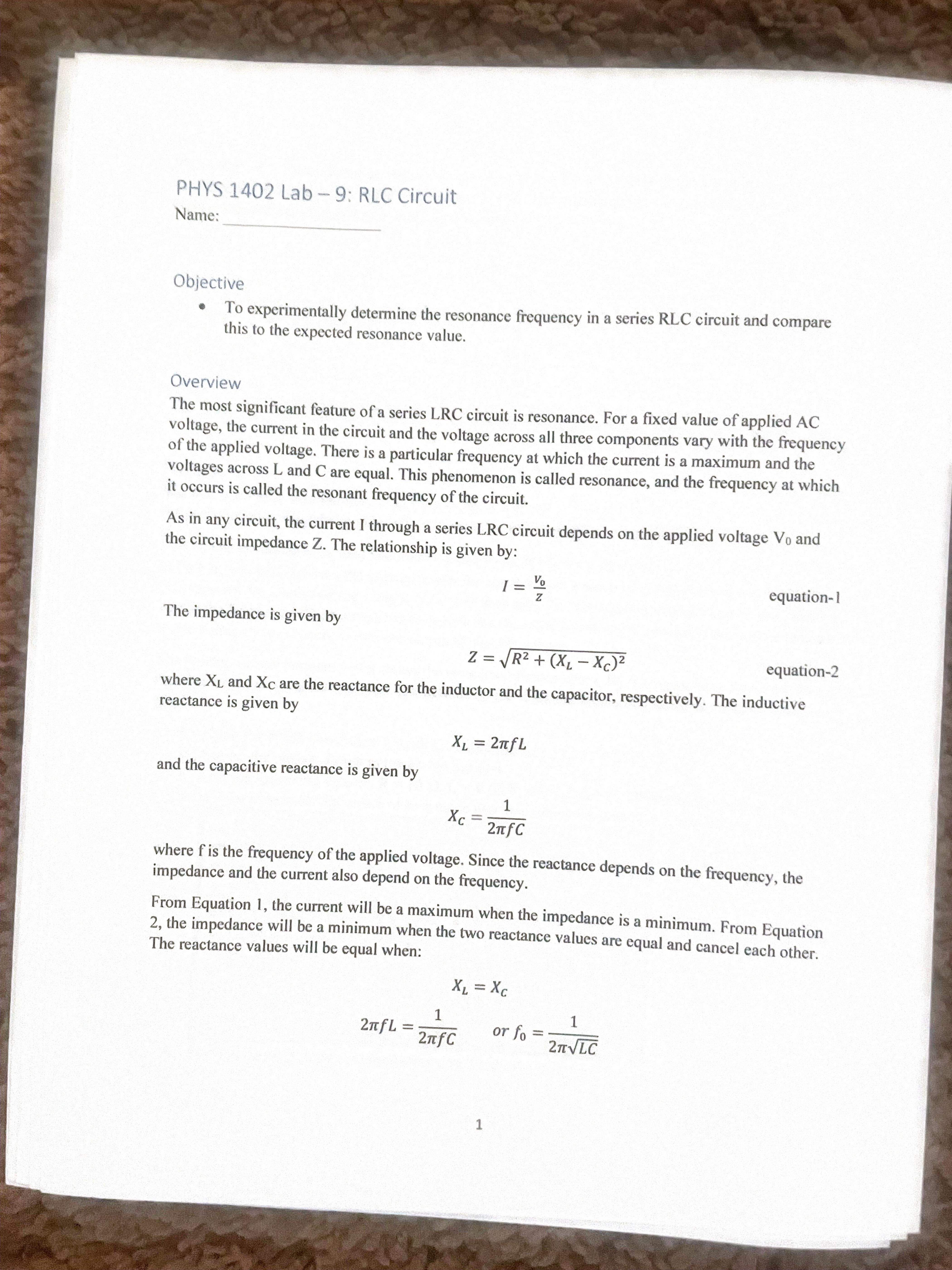
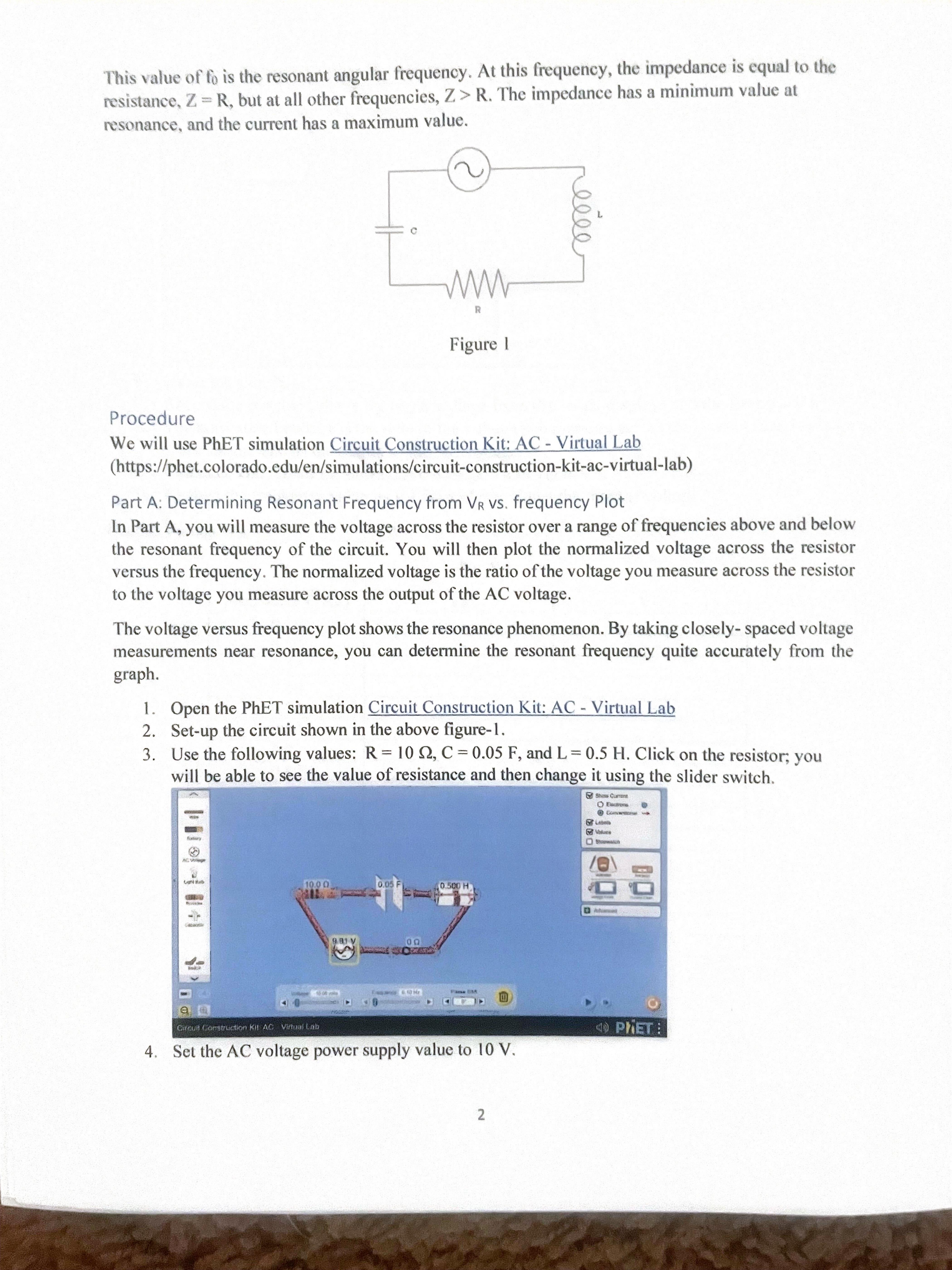
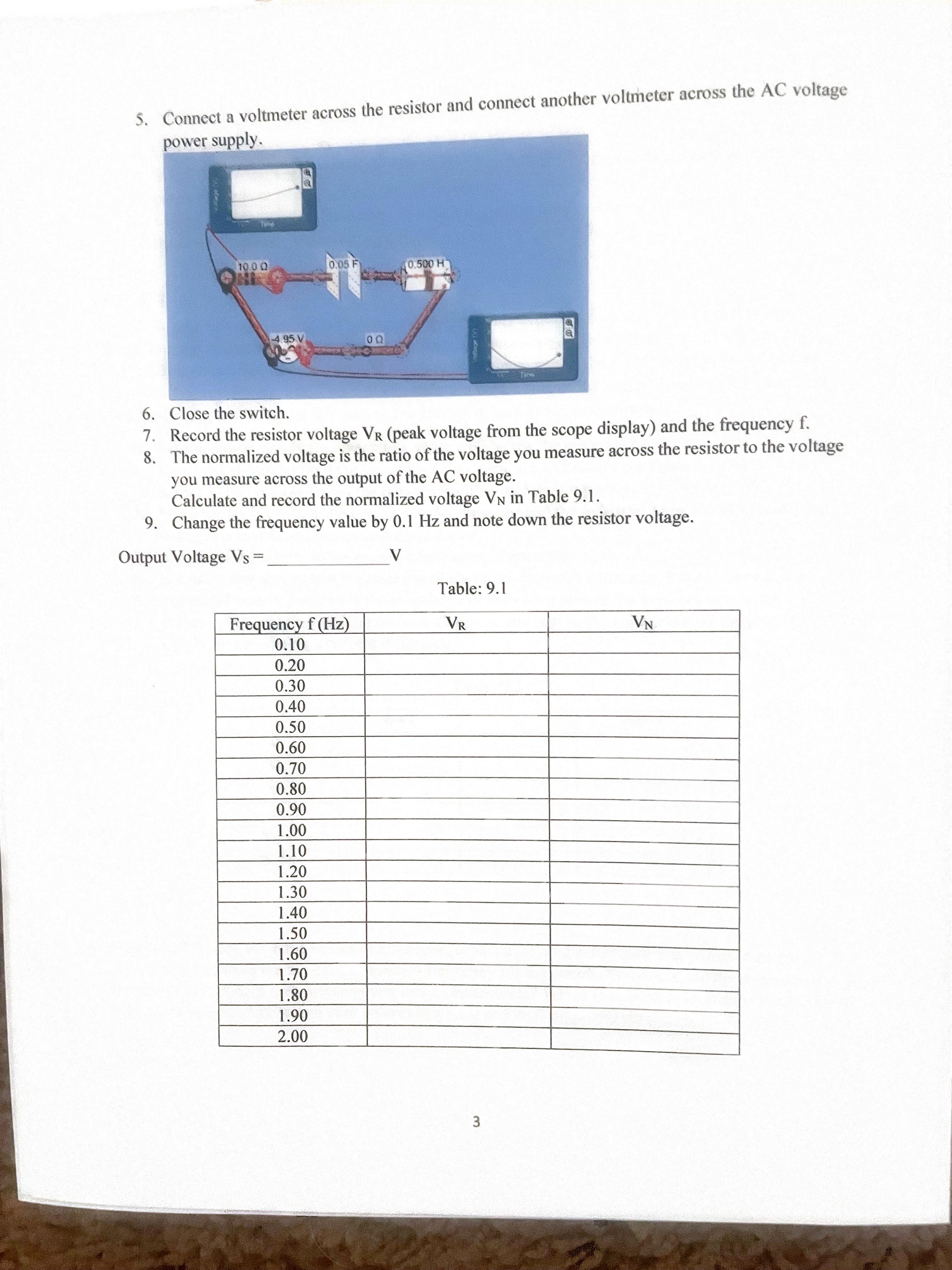
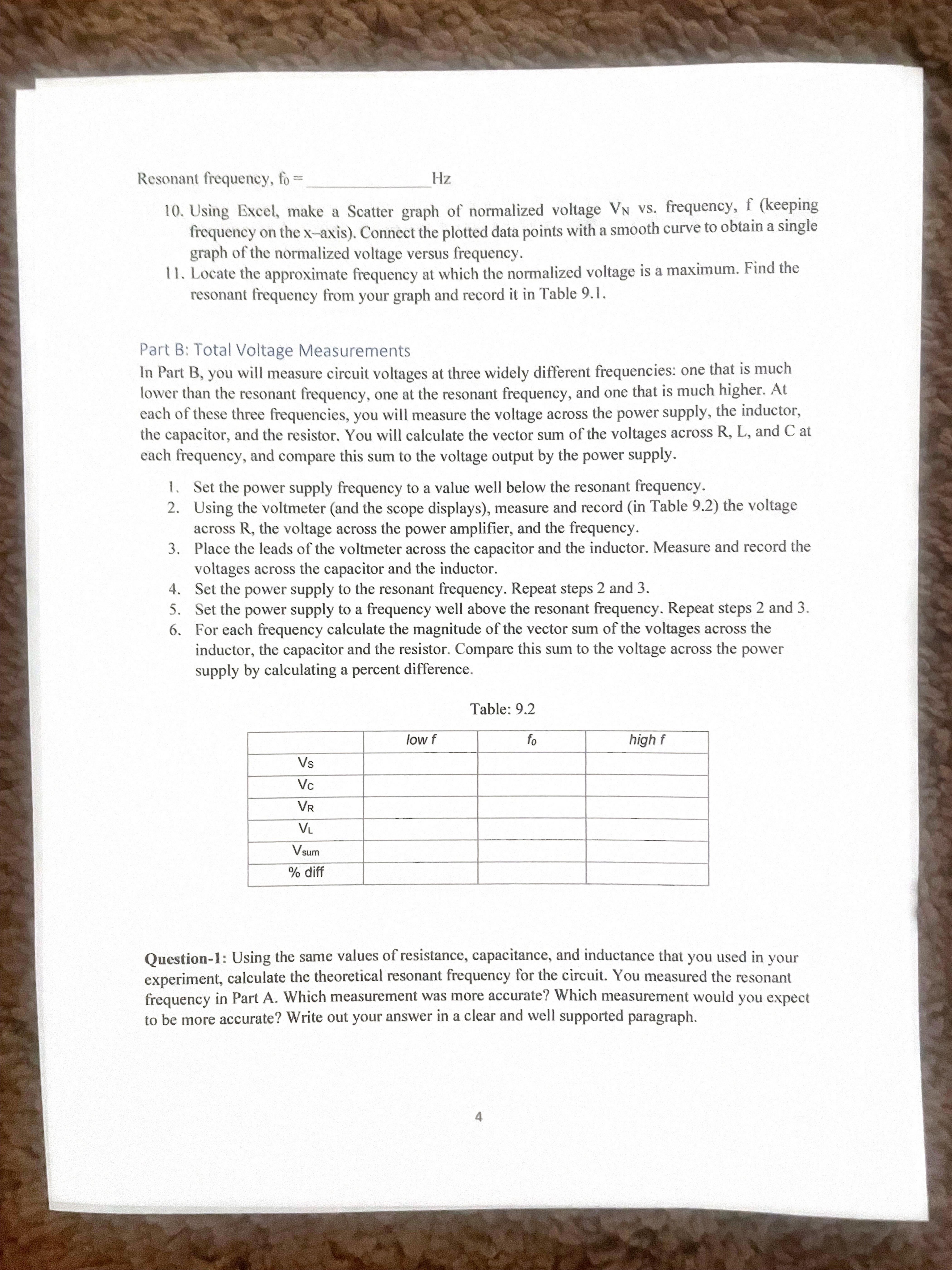
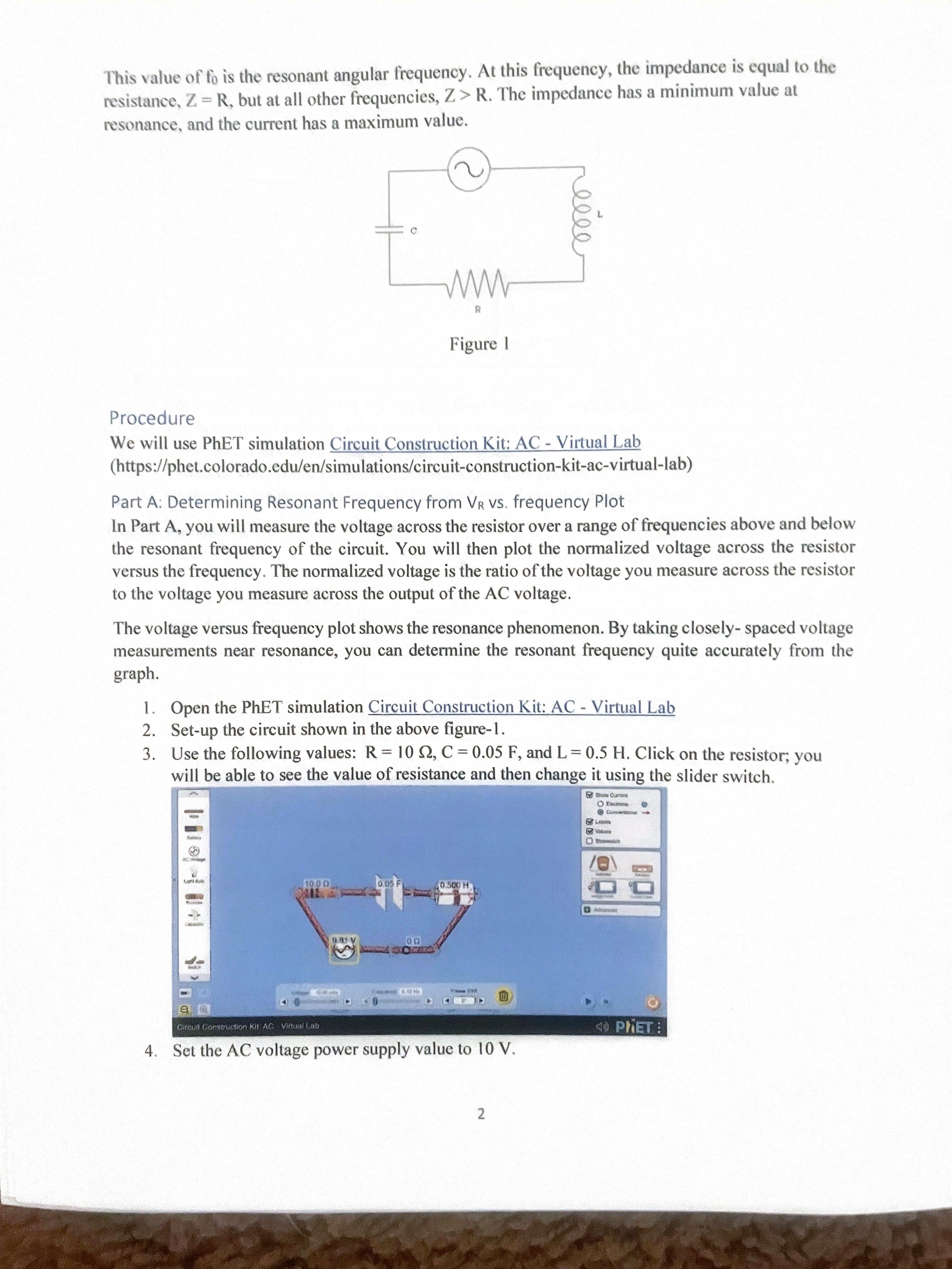
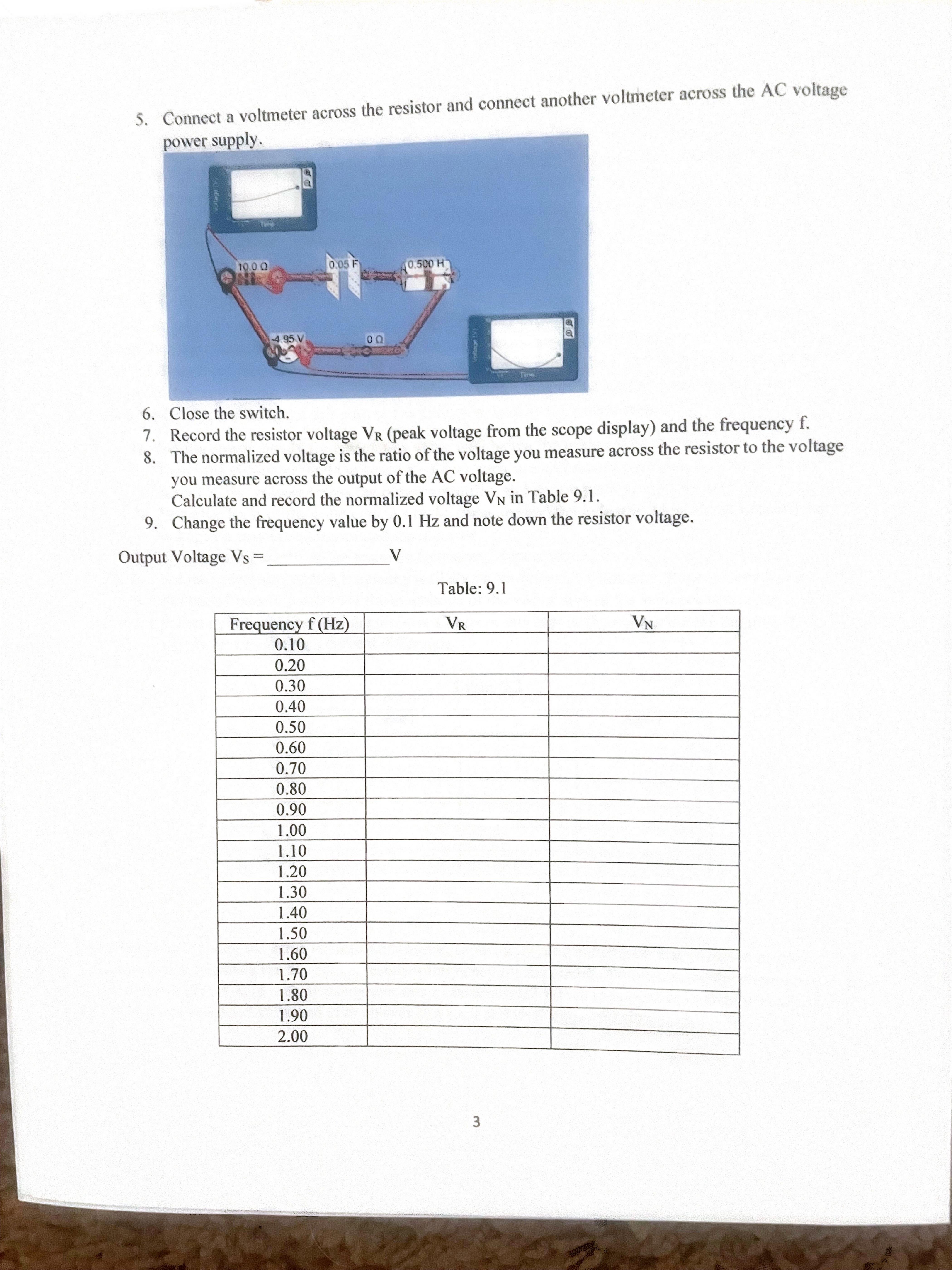
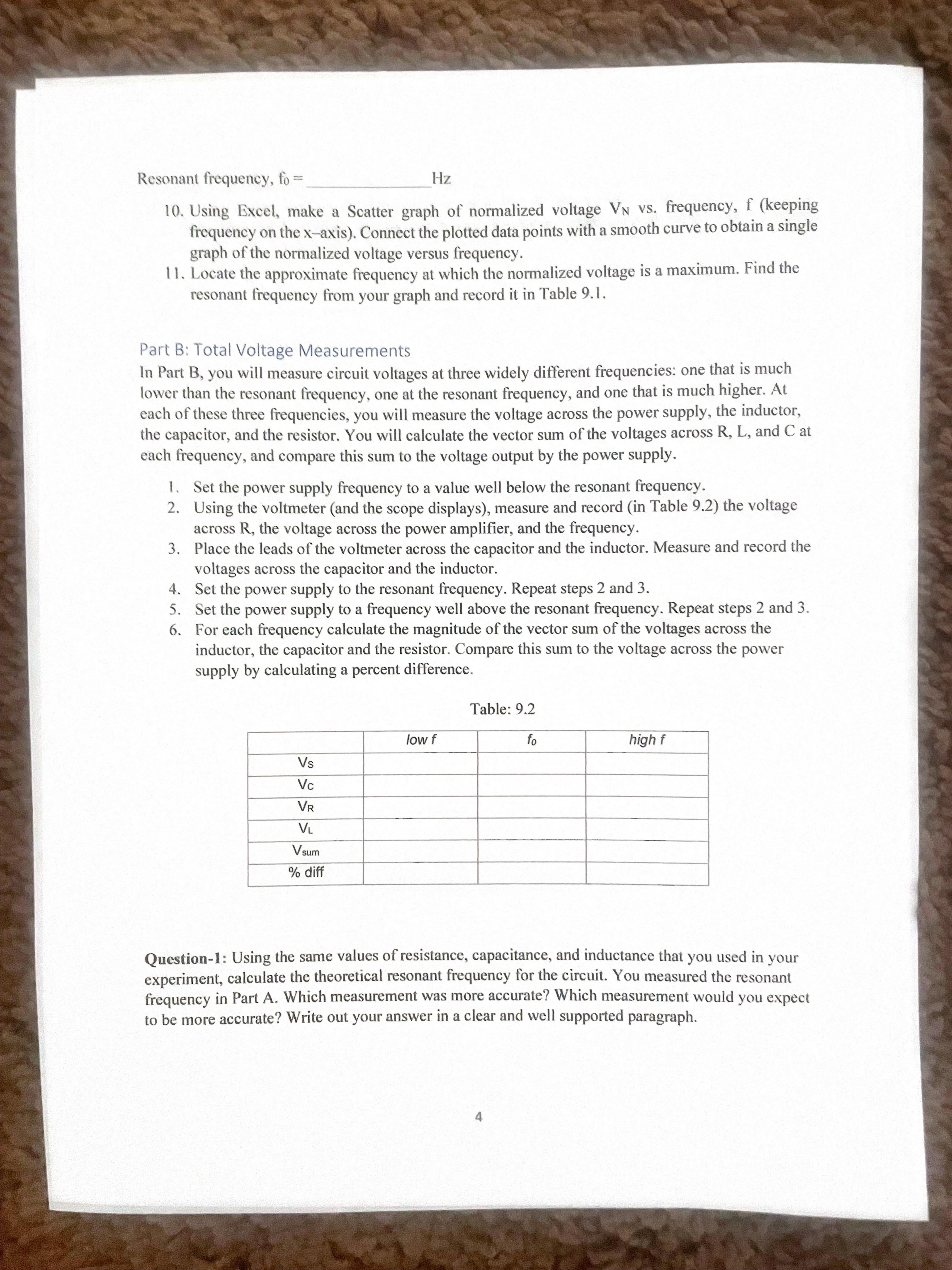
PHYS 1402 Lab - 9: RLC Circuit Name: Objective . To experimentally determine the resonance frequency in a series RLC circuit and compare this to the expected resonance value. Overview The most significant feature of a series LRC circuit is resonance. For a fixed value of applied AC voltage, the current in the circuit and the voltage across all three components vary with the frequency of the applied voltage. There is a particular frequency at which the current is a maximum and the voltages across L and C are equal. This phenomenon is called resonance, and the frequency at which it occurs is called the resonant frequency of the circuit. As in any circuit, the current I through a series LRC circuit depends on the applied voltage Vo and the circuit impedance Z. The relationship is given by: yo equation-1 The impedance is given by Z = VR2 + (XL - XC)2 equation-2 where XL and Xc are the reactance for the inductor and the capacitor, respectively. The inductive reactance is given by XL = 2nfL and the capacitive reactance is given by Xc= 2 T fC where f is the frequency of the applied voltage. Since the reactance depends on the frequency, the impedance and the current also depend on the frequency. From Equation 1, the current will be a maximum when the impedance is a minimum. From Equation 2, the impedance will be a minimum when the two reactance values are equal and cancel each other. The reactance values will be equal when: XL = XC 2nfL = 7 2 TL f C or fo = = 2TVLCThis wine of ii) is the resonant angular frequency. At this frequency, the impedance IS equal to the resistance. 7. =: R. but at all other frequencies, Z > R. The impedance has a minimum value at msonance. and the current has a maximum value. ' \\o k Figure I Procedure We will use PhET simulation Circuit Construction Kit: AC - Virtual Lab (https://phet.colorado.edu/en/simulations/cireuit-construction-kit-ac-virtual-lab) Part A; Determining Resonant Frequency from VR vs. frequency Plot In Part A, you will measure the voltage across the resistor over a range of frequencies above and below the resonant frequency of the circuit. You will then plot the normalized voltage across the resistor versus the frequency. The normalized voltage is the ratio of the voltage you measure across the resistor to the voltage you measure across the output of the AC voltage. The voltage versus frequency plot shows the resonance phenomenon. By taking closely- spaced voltage measurements near resonance, you can determine the resonant frequency quite accurately from the graph. 1. Open the PhET simulation Circuit Construction Kit: AC - Virtual Lab 2. Set-up the circuit shown in the above gure- 1. 3. Use the following values: R = l0 Q, C : 0.05 F, and L = 0.5 H. Click on the resistor; you will be able to see the value of resistance and then change it using the slider switch. 4. Set the AC voltage power supply value to to V. ' ' ' 'S * C voltax - 5 Connect a voltmeter across the resistor and connect another voltmeter acms the A Ur power supply. 6. Close the switch. 7. Record the resistor voltage VR (peak voltage from the scope display) and the frequency f . 8. The normalized voltage is the ratio of the voltage you measure across the resistor to the voltage you measure across the output of the AC voltage. Calculate and record the normalized voltage VN in Table 9.1. 9. Change the equency value by 0.1 Hz and note down the resistor voltage. Output Voltage vS = ____V Table: 9.! Resonant frequency, lb 1' Hz l0. Using Excel, make a Scatter graph of nomtalized voltage VN VS. frequency, f (keeping frequency on the x-~axis). Connect the plotth data points with a smooth curve to obtain a single graph ofthe normalized voltage versus frequency. 1 1. Locate the approximate frequency at which the nomialized voltage is a maximum. Find the resonant frequency from your graph and record it in Table 9.1. Part B: Total Voltage Measurements ln Part B, you will measure circuit voltages at three widely different frequencies: one that is much lower than the resonant frequency. one at the resonant frequency, and one that is much higher. At each ofthesc three frequencies, you will measure the voltage across the power supply, the inductor, the capacitor, and the resistor. You will calculate the vector sum of the voltages across R, L, and C at each frequency' and compare this sum to the voltage output by the power supply. I . Set the power supply frequency to a value well below the resonant frequency. 2. Using the voltmeter (and the scope displays), measure and record (in Table 9.2) the voltage across R, the voltage across the power amplier, and the frequency. Place the leads of the voltmeter across the capacitor and the inductor. Measure and record the voltages across the capacitor and the inductor. Set the power supply to the resonant frequency. Repeat steps 2 and 3. Set the power supply to a frequency well above the resonant frequency. Repeat steps 2 and 3. For each frequency calculate the magnitude of the vector sum of the voltages across the inductor, the capacitor and the resistor. Compare this sum to the voltage across the power supply by calculating a percent difference. Table: 9.2 Question-1: Using the same values of resistance, capacitance, and inductance that you used in your experiment, calculate the theoretical resonant frequency for the circuit. You measured the resonant frequency in Part A. Which measurement was more accurate? Which measurement would you expect to be more accurate? Write out your answer in a clear and well supported paragraph Questionl: Was the vector sum of the voltages across the inductor, the capacitor and the register equal to the applied voltage for any of the frequencies in Part B? What might cause these two voltages to be different. Write out your answer in a clear and well supported paragraph. Question-3: How does resistance affect the resonant frequency? Attach your graph


