

Question: I need help with this JAVA assignment to make a MIPS simulator that reads encoded MIPS instructions from a file and simulates the execution of
I need help with this JAVA assignment to make a MIPS simulator that reads encoded MIPS instructions from a file and simulates the execution of the instructions on a single cycle MIPS processor.
Most of the code is already made and uploaded on github https://github.uconn.edu/zhs04001/mips_sim_template_java
THE ONLY FILE THAT NEEDS TO BE MODIFIED IS the Core_SC file
Study the pseudo code at the end this document to have a global picture about the simulator and the work in Phase 1. Your main goal in this phase is to generate control signals and some other signals that do not depends on data. In the template, you can find a Signals class, which keeps all the signals you need to generate. You can call function print_signal_1() to print all the signals you need to generate in Phase 1. Table 2 lists important signals. You may find the following resources are helpful. The diagram of a MIPS processor we have studied is in Figure 4.24 in the textbook (also in f04-24.pdf). Some signals are not named in the textbook. Figures 4.12 and 4.13 specifies how the 4-bit ALU operation signal (the ALU control input signal in Figure 4.12 and the Operation signal in Figure 4.13) is generated from ALUOp and Funct field. Figure 4.16 (description of control signals) and Figure 4.18 (values of control signals) describe seven of the control signals generated by the main control unit. In this phase, you do not need to change run(). You only need to implement the following functions that simulates combinational modules. A function that generates signals by extracting bits from the encoded instruction (like opcode, rs, rt, rd, immediate, and so on). Main control unit. It takes the 6-bit opcode as input and generates the nine (9) signals. Note that you need support the addi instruction. Sign-extend unit. The unit extend a 16-bit 2s complement number to a 32-bit 2c complement number. Make sure you can handle both positive and negative values. In Java, the output is an int type. ALU control unit. The input of this unit is ALUOp form the main control unit and the funct field from the instruction. The output is the 4-bit ALU operation signal. A function that computes the branch address. A function that computes the jump address from (PC + 4) and the instruction. Some signals have dont care values so designers can simplify the circuit. In your implementation, set all dont care values to 0. Print out the value of all signals (by calling print_signal_1())
Test examples are
Address Code Basic Source
0x00400000 0x20010001 addi $1,$0,0x00000001 10 addi $1, $0, 1
0x00400004 0x0381e020 add $28,$28,$1 11 add $28, $28, $1
0x00400008 0x2002fffe addi $2,$0,0xfffffffe 13 addi $2, $0, -2
0x0040000c 0x0381e020 add $28,$28,$1 14 add $28, $28, $1
0x00400010 0x00221825 or $3,$1,$2 16 or $3, $1, $2
0x00400014 0x00232024 and $4,$1,$3 17 and $4, $1, $3
0x00400018 0x2005000a addi $5,$0,0x0000000a 19 addi $5, $0, 10
0x0040001c 0x10a0fff8 beq $5,$0,0xfffffff8 21 beq $5, $0, main
0x00400020 0x10a50005 beq $5,$5,0x00000005 22 beq $5, $5, end
0x00400024 0x00852822 sub $5,$4,$5 24 sub $5, $4, $5
0x00400028 0x20c603e8 addi $6,$6,0x000003e8 25 addi $6, $6, 1000
0x0040002c 0x8cc7fffc lw $7,0xfffffffc($6) 26 lw $7, -4($6)
0x00400030 0xacc80064 sw $8,0x00000064($6) 27 sw $8, 100($6)
0x00400034 0x0810000f j 0x0040003c 28 j exit
0x00400038 0x08100009 j 0x00400024 30 j back
Some background to help if needed:
Study the code and learn how to do things in the simulator. For example, access memory, read register files, use combinational modules like MUX. The program reads a list of instructions from a text file and store the instructions in instruction memory. The input files to your simulator are generated by MARS. You can find information on how to generate your own test files on the project site. Before the simulation starts, the program sets PC to the address of the first instruction in the instruction memory. The program then enters a function that simulates a single cycle MIPS processor. The function is located in core_sc file. It is the only file you need to modify. The function has a loop and each iteration of the loop simulates what is happening in a cycle. At the beginning of each cycle, all the registers are updated by calling the clock() method of regisers and register files. After the registers are updated, the program fetches instruction from the address in PC (which is just updated) and increase PC by 4. After the instruction is fetched, the program displays instruction address and instruction. The simulation completes when it has run for a specified number of cycles, or when the address of the instruction is out of range (i.e., no instructions are loaded to that address). The simulator is a console program. It takes a few arguments. MIPS_Sim input_file [options] The first argument is the input file that contains instructions. After the input file, you can specify some options. A nonnegative number. The number specifies the number of cycles the simulator runs. If it is 0, the simulation continues until PC is out of range. -v. This flag turns on the verbose mode. You can see the activities in register file and memory, for example, write to memory. -p1. This flag disables the phase 2 code. You can let simulator do Phase 1 only even if you have completed Phase 2.
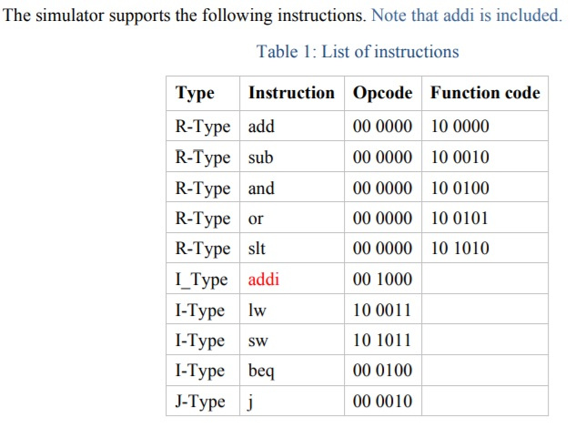
The simulator supports the following instructions. Note that addi is included. Table 1: List of instructions TypeInstruction Opcode Function code R-Type add R-Type sub R-Type and R-Type or R-Type slt I_Type addi I-Type Iw l-Type SW I-Type beq J-Type 00 0000 00 0000 00 0000 00 0000 00 0000 00 1000 10 0011 10 1011 00 0100 00 0010 10 0000 10 0010 10 0100 10 0101 10 1010 The simulator supports the following instructions. Note that addi is included. Table 1: List of instructions TypeInstruction Opcode Function code R-Type add R-Type sub R-Type and R-Type or R-Type slt I_Type addi I-Type Iw l-Type SW I-Type beq J-Type 00 0000 00 0000 00 0000 00 0000 00 0000 00 1000 10 0011 10 1011 00 0100 00 0010 10 0000 10 0010 10 0100 10 0101 10 1010
Step by Step Solution
There are 3 Steps involved in it

Get step-by-step solutions from verified subject matter experts