Answered step by step
Verified Expert Solution
Question
1 Approved Answer
I need the help of building this Simple Data Path Logic circuit by using Mulimedia Logic A data path is the path by which data


I need the help of building this Simple Data Path Logic circuit by using Mulimedia Logic
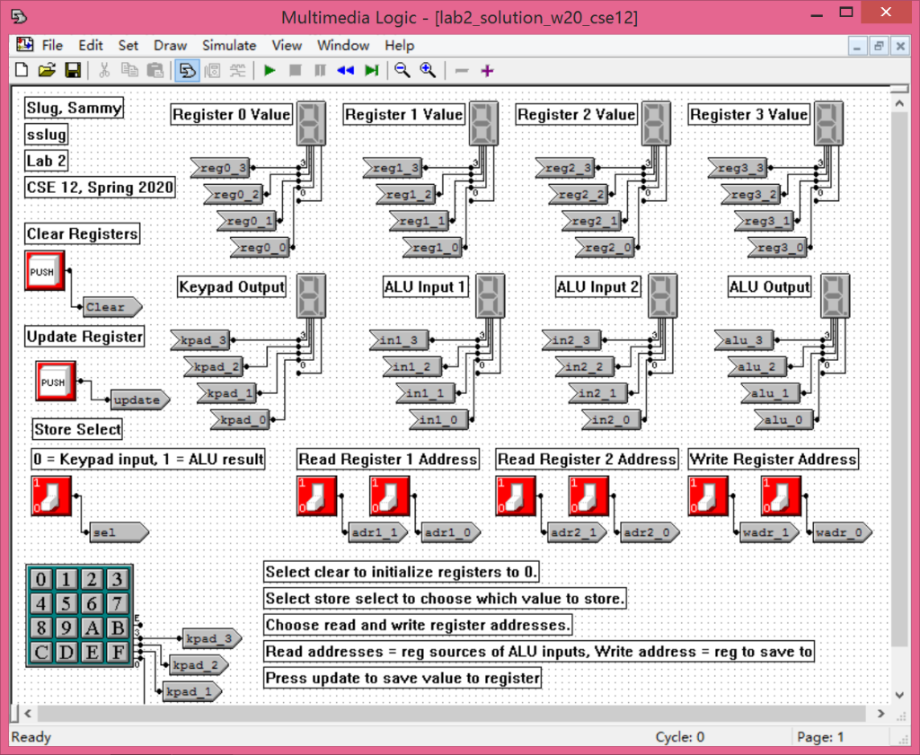
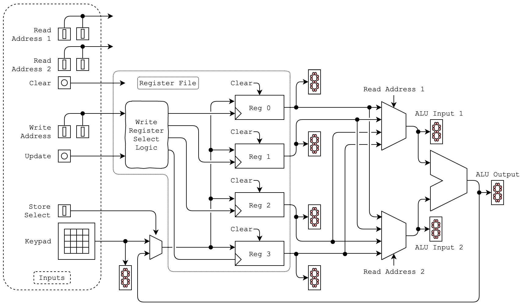
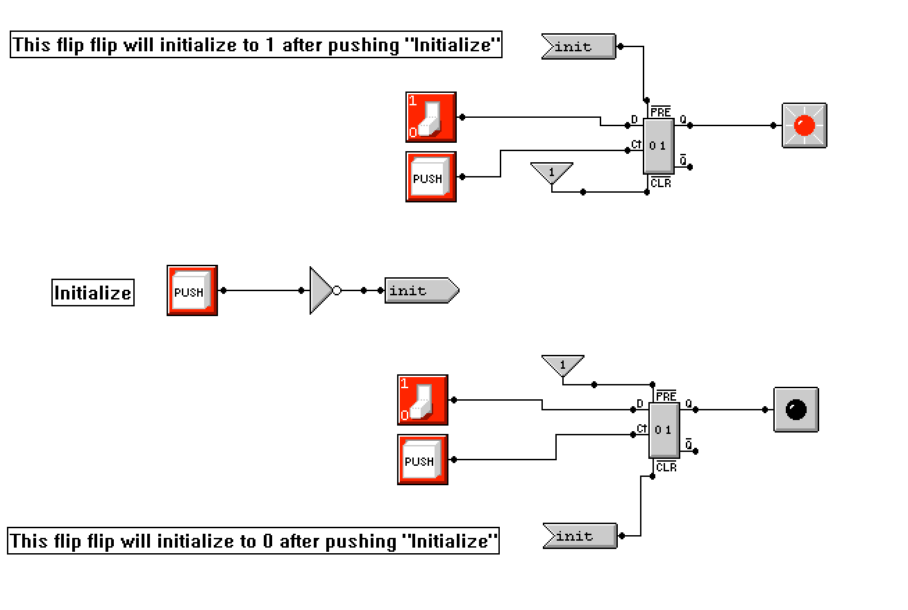
A data path is the path by which data flows in a system. In this lab, you will implement a simple data path with a register file, ALU, and user inputs. Each processor contains a register file that holds the registers used in program execution. Registers are fast access local variables that can change after every instruction. In this lab, you will be building a register file that contains four, 4-bit registers. Each of the four registers has an address (oboo -> Ob11) and stores a 4-bit value. The value saved to a destination register (write register) will be chosen from one of two sources, the keypad user input, or the output of the ALU. The ALU in this system is a 4-bit bitwise left arithmetic shift circuit that takes two of the register values as inputs (read registers). You may not use the MML library ALU and should instead build one out of muxes or logic gates. Template Build your lab starting with the template file provided in Google Drive. The template file contains the user interface. DO NOT MODIFY THE FIRST PAGE except for your name and CruzID (NOT your student ID number). Additional wires and logic circuits shall be drawn on subsequent pages. There are placeholder signal senders and receivers on the second page that you can use. You may remove these senders and receivers from the second page as you use them in your design. You are free to modify the template from the second page and add more pages. You are encouraged to add middle values to break a complicated circuit to several parts and add meaningful names to circuits to make them readable like the first page. 2 File Edit Set Multimedia Logic - [lab2_solution_w20_cse12] Draw Simulate View Window Help - + X Register 1 Value Register 2 Value Register 3 Value Slug, Sammy Register 0 Value sslug Lab 2 >rego CSE 12, Spring 2020 rego >regi reg2 reg3 regi >reg2 >reg3 >regi reg2 reg3 Clear Registers >rego reg1 reg2 reg3 PUSH Keypad Output ALU Input 1 ALU Input 2 ALU Output clear Update Register >kpad Sini_3 >in2 alu 3 Poruke >kpad ini PUSH >kpad_1 >ini update >kpad >in2 0 >alu o Store Select 0 = Keypad input, 1 = ALU result Read Register 1 Address Read Register 2 Address Write Register Address sel adri 1 adrio adr2 adr2 wadr wadr_0 0 1 2 3 4 5 6 7 8 9 AB Select clear to initialize registers to 0. Select store select to choose which value to store. Choose read and write register addresses. Read addresses = reg sources of ALU inputs, Write address = reg to save to Press update to save value to register kpad 3 CIDIE F kpad_2 kpad 1 Ready Cycle: 0 Page: 1 Read Address 1 Read Address 2 Clear Register File Clear Read Address 1 Reg 0 ALU Input 1 Write Address Clear Write Register Select Logic 8 Update Reg 1 ALU Output Clear 28 Reg 2 Store Select 8 Clear Keypad ALU Input 2 Reg 3 Read Address 2 Inputs This flip flip will initialize to 1 after pushing 'Initialize" >init 1 FRE a01 PUSH CLR Initialize PUSH init 1 PRE D O CH 01 PUSH CLR >init This flip flip will initialize to 0 after pushing 'Initialize" A data path is the path by which data flows in a system. In this lab, you will implement a simple data path with a register file, ALU, and user inputs. Each processor contains a register file that holds the registers used in program execution. Registers are fast access local variables that can change after every instruction. In this lab, you will be building a register file that contains four, 4-bit registers. Each of the four registers has an address (oboo -> Ob11) and stores a 4-bit value. The value saved to a destination register (write register) will be chosen from one of two sources, the keypad user input, or the output of the ALU. The ALU in this system is a 4-bit bitwise left arithmetic shift circuit that takes two of the register values as inputs (read registers). You may not use the MML library ALU and should instead build one out of muxes or logic gates. Template Build your lab starting with the template file provided in Google Drive. The template file contains the user interface. DO NOT MODIFY THE FIRST PAGE except for your name and CruzID (NOT your student ID number). Additional wires and logic circuits shall be drawn on subsequent pages. There are placeholder signal senders and receivers on the second page that you can use. You may remove these senders and receivers from the second page as you use them in your design. You are free to modify the template from the second page and add more pages. You are encouraged to add middle values to break a complicated circuit to several parts and add meaningful names to circuits to make them readable like the first page. 2 File Edit Set Multimedia Logic - [lab2_solution_w20_cse12] Draw Simulate View Window Help - + X Register 1 Value Register 2 Value Register 3 Value Slug, Sammy Register 0 Value sslug Lab 2 >rego CSE 12, Spring 2020 rego >regi reg2 reg3 regi >reg2 >reg3 >regi reg2 reg3 Clear Registers >rego reg1 reg2 reg3 PUSH Keypad Output ALU Input 1 ALU Input 2 ALU Output clear Update Register >kpad Sini_3 >in2 alu 3 Poruke >kpad ini PUSH >kpad_1 >ini update >kpad >in2 0 >alu o Store Select 0 = Keypad input, 1 = ALU result Read Register 1 Address Read Register 2 Address Write Register Address sel adri 1 adrio adr2 adr2 wadr wadr_0 0 1 2 3 4 5 6 7 8 9 AB Select clear to initialize registers to 0. Select store select to choose which value to store. Choose read and write register addresses. Read addresses = reg sources of ALU inputs, Write address = reg to save to Press update to save value to register kpad 3 CIDIE F kpad_2 kpad 1 Ready Cycle: 0 Page: 1 Read Address 1 Read Address 2 Clear Register File Clear Read Address 1 Reg 0 ALU Input 1 Write Address Clear Write Register Select Logic 8 Update Reg 1 ALU Output Clear 28 Reg 2 Store Select 8 Clear Keypad ALU Input 2 Reg 3 Read Address 2 Inputs This flip flip will initialize to 1 after pushing 'Initialize" >init 1 FRE a01 PUSH CLR Initialize PUSH init 1 PRE D O CH 01 PUSH CLR >init This flip flip will initialize to 0 after pushing 'InitializeStep by Step Solution
There are 3 Steps involved in it
Step: 1

Get Instant Access to Expert-Tailored Solutions
See step-by-step solutions with expert insights and AI powered tools for academic success
Step: 2

Step: 3

Ace Your Homework with AI
Get the answers you need in no time with our AI-driven, step-by-step assistance
Get Started


