Question: I need the MATLAB code for this problem and model if possible, please. V (s) PI kpwm 1/R 1 +ST, kr ke (a) 8.3 In


I need the MATLAB code for this problem and model if possible, please.
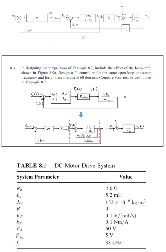
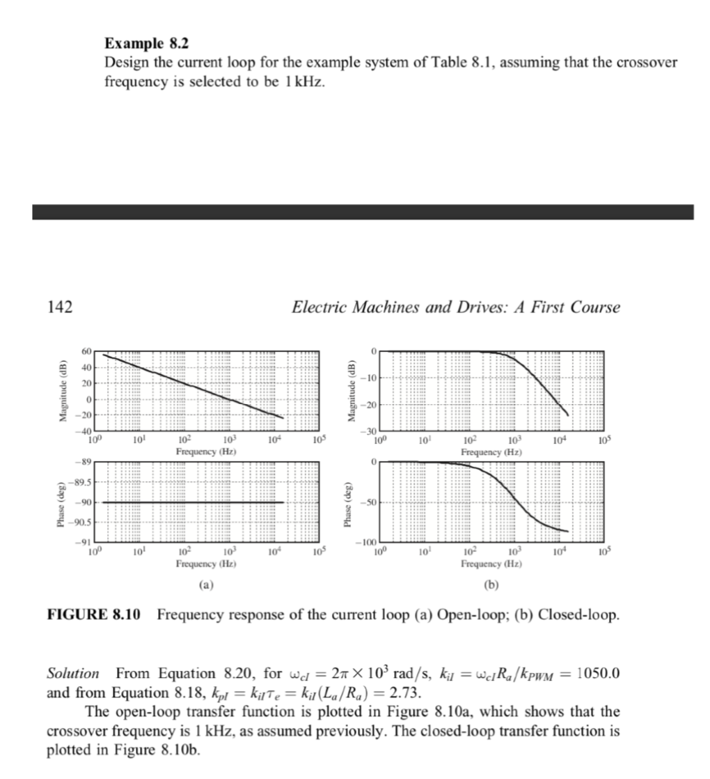
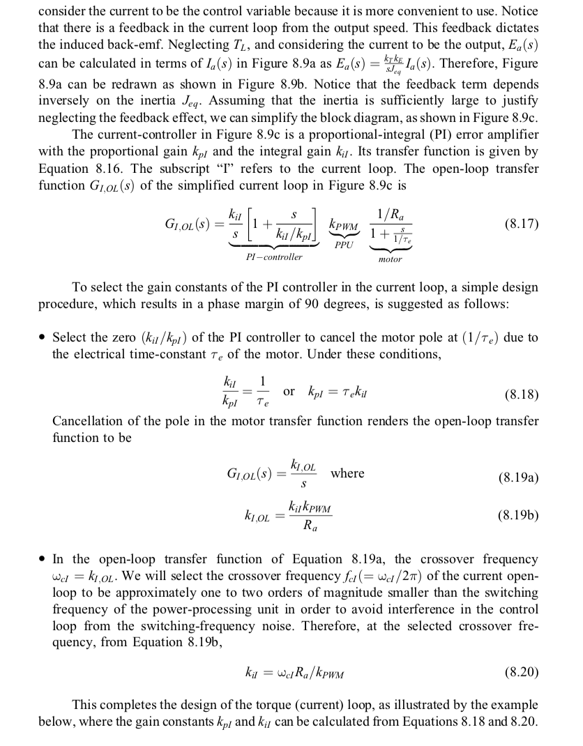
V (s) PI kpwm 1/R 1 +ST, kr ke (a) 8.3 In designing the torque loop of Example 8.2, include the effect of the back-emf, shown in Figure 8.9a. Design a PI controller for the same open-loop crossover frequency and for a phase margin of 60 degrees. Compare your results with those in Example 8.2. V.) 1(s) skpl IR ki 1.) lv.) PI KIR | Ea(s) kete 1.) TABLE 8.1 DC-Motor Drive System System Parameter Value Ra La Jeg B KE kt Vd ri fs 2.0 12 5.2 mH 152 x 10-kg.mp 0 0.1 V/(rad/s) 0.1 Nm/A 60 V 5 V 33 kHz Example 8.2 Design the current loop for the example system of Table 8.1, assuming that the crossover frequency is selected to be 1 kHz. 142 Electric Machines and Drives: A First Course 60 0 40 -10 20 Magnitude (dB) Magnitude (dB) 0 -20 40 100 101 10- 105 -30 100 10 10+ 105 10- 10 Frequency (Hz) 102 10 Frequency (Hz) -89 0 -89.5 Phase (deg) -90 Phase (deg) -50 -90.5 -91 10P 10 10 105 -100 100 10 10" 105 102 10 Frequency (Hz) 102 102 Frequency (Hz) (b) (a) FIGURE 8.10 Frequency response of the current loop (a) Open-loop; (b) Closed-loop. Solution From Equation 8.20, for wd = 21 X 109 rad/s, kij = wc] Rn/kpwm = 1050.0 and from Equation 8.18, kpl = kilte = k/(La/Rq) = 2.73. The open-loop transfer function is plotted in Figure 8.10a, which shows that the crossover frequency is 1 kHz, as assumed previously. The closed-loop transfer function is plotted in Figure 8.10b. consider the current to be the control variable because it is more convenient to use. Notice that there is a feedback in the current loop from the output speed. This feedback dictates the induced back-emf. Neglecting T, and considering the current to be the output, Ea(s) can be calculated in terms of In(s) in Figure 8.9a as Ea(s) = kyken 1, (s). Therefore, Figure 8.9a can be redrawn as shown in Figure 8.9b. Notice that the feedback term depends inversely on the inertia Jeg. Assuming that the inertia is sufficiently large to justify neglecting the feedback effect, we can simplify the block diagram, as shown in Figure 8.9c. The current-controller in Figure 8.9c is a proportional-integral (PI) error amplifier with the proportional gain kp, and the integral gain kil. Its transfer function is given by Equation 8.16. The subscript I refers to the current loop. The open-loop transfer function G1,OL(s) of the simplified current loop in Figure 8.9c is kil GLOL(s) S 1 + ki/kpl] PI-controller ki til (8.17) 1/R 1+1 , PPU motor To select the gain constants of the PI controller in the current loop, a simple design procedure, which results in a phase margin of 90 degrees, is suggested as follows: Select the zero (kir/kpl) of the PI controller to cancel the motor pole at (1/Te) due to the electrical time-constant Te of the motor. Under these conditions, 1 = ki or kpl = Tekil kpl Te (8.18) Cancellation of the pole in the motor transfer function renders the open-loop transfer function to be k.OL GOL(S) where (8.19a) S kijkPWM ki,OL = Ra (8.19b) In the open-loop transfer function of Equation 8.19a, the crossover frequency We = k1,ol. We will select the crossover frequency fel(= wc/27) of the current open- loop to be approximately one to two orders of magnitude smaller than the switching frequency of the power-processing unit in order to avoid interference in the control loop from the switching-frequency noise. Therefore, at the selected crossover fre- quency, from Equation 8.196, ki = wcR/kPWM (8.20) This completes the design of the torque (current) loop, as illustrated by the example below, where the gain constants kp, and ki can be calculated from Equations 8.18 and 8.20. V (s) PI kpwm 1/R 1 +ST, kr ke (a) 8.3 In designing the torque loop of Example 8.2, include the effect of the back-emf, shown in Figure 8.9a. Design a PI controller for the same open-loop crossover frequency and for a phase margin of 60 degrees. Compare your results with those in Example 8.2. V.) 1(s) skpl IR ki 1.) lv.) PI KIR | Ea(s) kete 1.) TABLE 8.1 DC-Motor Drive System System Parameter Value Ra La Jeg B KE kt Vd ri fs 2.0 12 5.2 mH 152 x 10-kg.mp 0 0.1 V/(rad/s) 0.1 Nm/A 60 V 5 V 33 kHz Example 8.2 Design the current loop for the example system of Table 8.1, assuming that the crossover frequency is selected to be 1 kHz. 142 Electric Machines and Drives: A First Course 60 0 40 -10 20 Magnitude (dB) Magnitude (dB) 0 -20 40 100 101 10- 105 -30 100 10 10+ 105 10- 10 Frequency (Hz) 102 10 Frequency (Hz) -89 0 -89.5 Phase (deg) -90 Phase (deg) -50 -90.5 -91 10P 10 10 105 -100 100 10 10" 105 102 10 Frequency (Hz) 102 102 Frequency (Hz) (b) (a) FIGURE 8.10 Frequency response of the current loop (a) Open-loop; (b) Closed-loop. Solution From Equation 8.20, for wd = 21 X 109 rad/s, kij = wc] Rn/kpwm = 1050.0 and from Equation 8.18, kpl = kilte = k/(La/Rq) = 2.73. The open-loop transfer function is plotted in Figure 8.10a, which shows that the crossover frequency is 1 kHz, as assumed previously. The closed-loop transfer function is plotted in Figure 8.10b. consider the current to be the control variable because it is more convenient to use. Notice that there is a feedback in the current loop from the output speed. This feedback dictates the induced back-emf. Neglecting T, and considering the current to be the output, Ea(s) can be calculated in terms of In(s) in Figure 8.9a as Ea(s) = kyken 1, (s). Therefore, Figure 8.9a can be redrawn as shown in Figure 8.9b. Notice that the feedback term depends inversely on the inertia Jeg. Assuming that the inertia is sufficiently large to justify neglecting the feedback effect, we can simplify the block diagram, as shown in Figure 8.9c. The current-controller in Figure 8.9c is a proportional-integral (PI) error amplifier with the proportional gain kp, and the integral gain kil. Its transfer function is given by Equation 8.16. The subscript I refers to the current loop. The open-loop transfer function G1,OL(s) of the simplified current loop in Figure 8.9c is kil GLOL(s) S 1 + ki/kpl] PI-controller ki til (8.17) 1/R 1+1 , PPU motor To select the gain constants of the PI controller in the current loop, a simple design procedure, which results in a phase margin of 90 degrees, is suggested as follows: Select the zero (kir/kpl) of the PI controller to cancel the motor pole at (1/Te) due to the electrical time-constant Te of the motor. Under these conditions, 1 = ki or kpl = Tekil kpl Te (8.18) Cancellation of the pole in the motor transfer function renders the open-loop transfer function to be k.OL GOL(S) where (8.19a) S kijkPWM ki,OL = Ra (8.19b) In the open-loop transfer function of Equation 8.19a, the crossover frequency We = k1,ol. We will select the crossover frequency fel(= wc/27) of the current open- loop to be approximately one to two orders of magnitude smaller than the switching frequency of the power-processing unit in order to avoid interference in the control loop from the switching-frequency noise. Therefore, at the selected crossover fre- quency, from Equation 8.196, ki = wcR/kPWM (8.20) This completes the design of the torque (current) loop, as illustrated by the example below, where the gain constants kp, and ki can be calculated from Equations 8.18 and 8.20
Step by Step Solution
There are 3 Steps involved in it

Get step-by-step solutions from verified subject matter experts


