

Question
I need verilog code for this. Thank you Part 3 is completed with this verilog code: // Verilog Code for MOD10 Counter //Decade Counter module
I need verilog code for this. Thank you
Part 3 is completed with this verilog code:
// Verilog Code for MOD10 Counter
//Decade Counter module mod10_upc( dc,clock,reset ); output [ 3:0 ] dc; reg [ 3:0 ] dc; input clock,reset;
always @( posedge clock or negedge reset ) begin if( ~reset ) dc=4b0;
// Condition to end count after MOD10 else if( dc==4b1001 ) dc=4b0; else dc=dc+1b1; end
endmodule
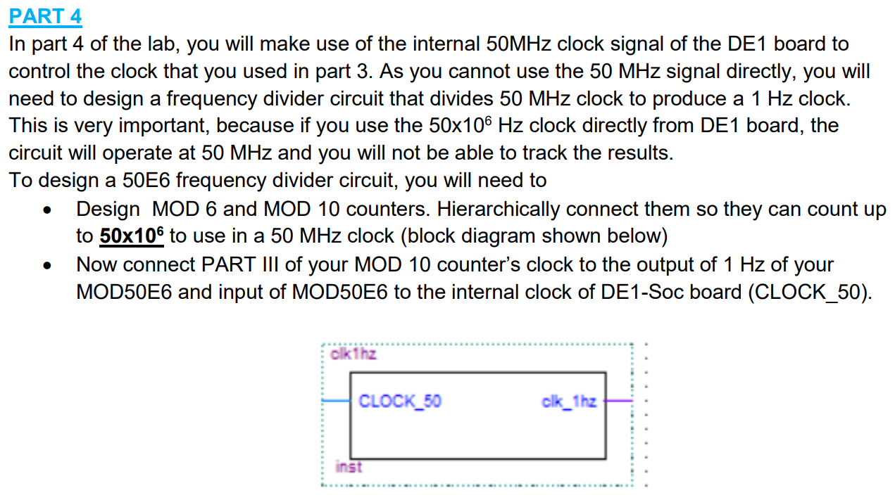
PART 4 In part 4 of the lab, you will make use of the internal 50MHz clock signal of the DE1 board to control the clock that you used in part 3. As you cannot use the 50 MHz signal directly, you will need to design a frequency divider circuit that divides 50 MHz clock to produce a 1 Hz clock. This is very important, because if you use the 50x106 Hz clock directly from DE1 board, the circuit will operate at 50 MHz and you will not be able to track the results. To design a 50E6 frequency divider circuit, you will need to Design MOD 6 and MOD 10 counters. Hierarchically connect them so they can count up to 50x106 to use in a 50 MHz clock (block diagram shown below) Now connect PART III of your MOD 10 counter's clock to the output of 1 Hz of your MOD50E6 and input of MOD50E6 to the internal clock of DE1-Soc board (CLOCK_50). . clk 1hz CLOCK_50 clk_1hz inst PART 4 In part 4 of the lab, you will make use of the internal 50MHz clock signal of the DE1 board to control the clock that you used in part 3. As you cannot use the 50 MHz signal directly, you will need to design a frequency divider circuit that divides 50 MHz clock to produce a 1 Hz clock. This is very important, because if you use the 50x106 Hz clock directly from DE1 board, the circuit will operate at 50 MHz and you will not be able to track the results. To design a 50E6 frequency divider circuit, you will need to Design MOD 6 and MOD 10 counters. Hierarchically connect them so they can count up to 50x106 to use in a 50 MHz clock (block diagram shown below) Now connect PART III of your MOD 10 counter's clock to the output of 1 Hz of your MOD50E6 and input of MOD50E6 to the internal clock of DE1-Soc board (CLOCK_50). . clk 1hz CLOCK_50 clk_1hz instStep by Step Solution
There are 3 Steps involved in it
Step: 1

Get Instant Access to Expert-Tailored Solutions
See step-by-step solutions with expert insights and AI powered tools for academic success
Step: 2

Step: 3
Ace Your Homework with AI
Get the answers you need in no time with our AI-driven, step-by-step assistance
Get Started
Database 101
Authors: Guy Kawasaki
1st Edition
0938151525, 978-0938151524