

Question
I want an electronic drawing of the ER diagram, & MAP diagram, & code SQL , and a screenshot of the output and this data
I want an electronic drawing of the ER diagram, & MAP diagram, & code SQL , and a screenshot of the output and this data below
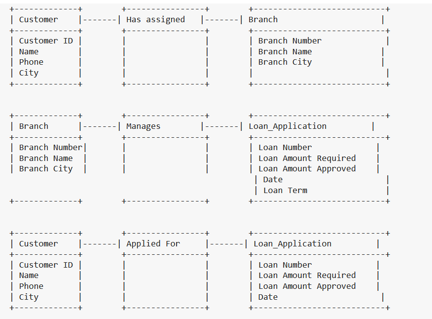
ER Diagram:
[Customer(Customer ID, Name, Phone, City)] --[Has assigned]--> [Branch(Branch Number, Branch Name, Branch City)]
[Branch(Branch Number, Branch Name, Branch City)] --[Manages]--> [Loan_Application(Loan Number, Loan Amount Required, Loan Amount Approved, Date, Loan Term)]
[Customer(Customer ID, Name, Phone, City)] --[Applied For]--> [Loan_Application(Loan Number, Loan Amount Required, Loan Amount Approved, Date, Loan Term)]
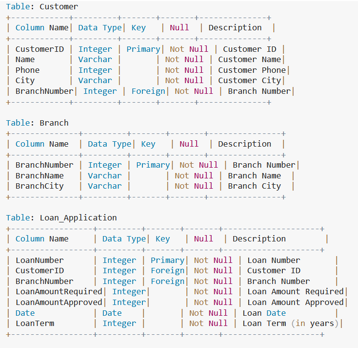
Relational Model:
Customer(CustomerID, Name, Phone, City, BranchNumber)
Branch(BranchNumber, BranchName, BranchCity)
Loan_Application(LoanNumber, CustomerID, BranchNumber, LoanAmountRequired, LoanAmountApproved, Date, LoanTerm)
a text-based ER diagram for the given scenario:
a text-based representation of the tables with columns and keys for the relational model:
The ER diagram can be mapped to the relational model by creating tables for each entity and defining columns for each attribute. The relationships between the entities can be represented through foreign keys.
For example, the Customer entity can be represented as a table with columns for CustomerID, Name, Phone, City, and a foreign key to the Branch table (BranchNumber).
The Branch entity can be represented as a table with columns for BranchNumber, BranchName, and BranchCity.
The Loan_Application entity can be represented as a table with columns for LoanNumber, CustomerID (as a foreign key to the Customer table), BranchNumber (as a foreign key to the Branch table), LoanAmountRequired, LoanAmountApproved, Date, and LoanTerm.
The relationships between the entities can be represented through the foreign key constraints in the tables. For example, the relationship between Customer and Branch is represented by the foreign key BranchNumber in the Customer table, which references the primary key BranchNumber in the Branch table. Similarly, the relationship between Loan_Application and Customer is represented by the foreign key CustomerID in the Loan_Application table, which references the primary key CustomerID in the Customer table. The relationship between Loan_Application and Branch is represented by the foreign key BranchNumber in the Loan_Application table, which references the primary key BranchNumber in the Branch table.
Tables for each entity: Each entity in the ER diagram is represented as a table in the relational model. In this case, the entities are Customer, Branch, and Loan_Application.
Columns for each attribute: Each attribute of an entity is represented as a column in the corresponding table. For example, the Customer entity has attributes for CustomerID, Name, Phone, and City, so the Customer table has columns for each of these attributes.
Foreign keys to represent relationships: The relationships between the entities in the ER diagram are represented through foreign keys in the relational model. For example, the relationship between Customer and Branch is represented by a foreign key BranchNumber in the Customer table, which references the primary key BranchNumber in the Branch table.
Relationships represented through foreign key constraints: The relationships between the entities in the relational model are defined through foreign key constraints. For example, the CustomerID column in the Loan_Application table is a foreign key that references the CustomerID primary key in the Customer table, representing the relationship between a loan application and the customer it is managed by.
Normalization of data: The relational model also ensures that the data is stored in a normalized manner, i.e. with minimal redundancy and consistency of data, which helps to minimize data anomalies and improves data integrity.
Table: Customer Table: CustomerStep by Step Solution
There are 3 Steps involved in it
Step: 1

Get Instant Access to Expert-Tailored Solutions
See step-by-step solutions with expert insights and AI powered tools for academic success
Step: 2

Step: 3
Ace Your Homework with AI
Get the answers you need in no time with our AI-driven, step-by-step assistance
Get Started
Google Drive And Docs Ultimate Users Guide Beginners Illustrative Guide To Google Drive Docs Sheets And Slides
Authors: Charles Derrick
1st Edition
B089M2J7S7, 979-8651245017