

Answered step by step
Verified Expert Solution
Question
1 Approved Answer
Imagine that you are part of a team designing an industrial manufacturing robot. The robot has a base which sits on the floor. Attached to
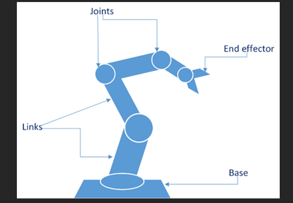
Imagine that you are part of a team designing an industrial manufacturing robot. The robot has a base which sits on the floor. Attached to the base is a robotic arm, called the manipulator. The manipulator consists of linksparts which are connected together via articulated joints. At the end of the manipulator is an additional joint, and an endeffector, which is a tool device that the robot uses in its current job role. A sketch of the robot is shown in Figure
The first joint is where the robotic arm joins the base. This joint can rotate, so that the robot can orient itself in different directions. The next joints are articulated like a human elbow, to allow the arm to move up and down, or forwards and backwards. The final joint allows the endeffector to rotate through degrees. The robot is fitted with electric motors called servomotors, which can provide precise movement. Each joint requires one servomotor to provide movement. Each servomotor also has a sensor called an encoder; the encoder allows the servomotor to monitor its own movements accurately.
In order to ensure it can work safely alongside humans, the robot is equipped with a Proximity Sensor that can detect when humans are in the vicinity, and their current distance from the robot.
Finally, the robot has a central controller which provides all the required control logic ie all the decisionmaking as well as a power supply.
Here is the sequence of actions carried out in order to move the robot.
The controller selects a desired pose for the manipulator.
The controller calculates what movements are required from each joint.
The controller sends an instruction to each of the servomotors, stating the desired amount of movement that each individual servomotor should deliver.
Each servomotor receives an individual instruction and applies power to the motor to start moving.
Each servomotor continually collects data from its own encoder. This allows the servomotor to monitor how close it is to the final instructed position. When the encoder data shows that the limb has reached its instructed final position, the servomotor stops.
Each servomotor returns a confirmation to the Controller that the motor has stopped in its requested final position.
Questions
The controller has chosen a new pose which requires movement from only one servomotor. All other servomotors will remain stationary. Produce an activity diagram showing the sequence of actions that are carried out when the robot moves position, beginning with the controller selecting a new pose. Use swimlanes to indicate which system element carries out which action.
Produce an Internal Block Diagram IBD showing the Manipulator and its subparts. Identify the interactions between the subparts when the Manipulator moves position. You do not need to use ports on the internal parts of your model, but if your model includes interactions with entities outside the Manipulator you should define these formally using ports and flows. Use an InterfaceBlock to define any ports.
The robot also has a Distancing Unit, implemented entirely in software. The Distancing unit accepts inputs from the Proximity Sensor, and calculates a minimum safe distance between the robot and detected human. The calculation to work out minimum safe distance is complex. It can be calculated using constants eg average human walking speed, worse case robot speed etc. or dynamic data collected from sensors eg current robot speed A safety specialist at your company has added the requirement: When the Distancing Unit detects that minimum safe distance has been violated, the robot should stop moving within n milliseconds. The Distancing Unit should deliver high reliability and high availability.
a Suggest an appropriate architectural pattern you could use to implement the Distancing Unit. Write a few lines to justify your decision.
b Produce a diagram to illustrate how your selected pattern could be used to implement the Distancing Unit. You may choose a suitable diagram type eg an IBD, an activity diagram
Your team will implement a watchdog timer to ensure that the requirement to stop within n milliseconds is satisfied. Produce an activity diagram to show how you would implement the watchdog timer in this case. Your diagram should indicate which system elements in the robot carry out the watchdog timer functionality.
Step by Step Solution
There are 3 Steps involved in it
Step: 1

Get Instant Access to Expert-Tailored Solutions
See step-by-step solutions with expert insights and AI powered tools for academic success
Step: 2

Step: 3
Ace Your Homework with AI
Get the answers you need in no time with our AI-driven, step-by-step assistance
Get Started
Advances In Spatial And Temporal Databases 10th International Symposium Sstd 2007 Boston Ma Usa July 2007 Proceedings Lncs 4605
Authors: Dimitris Papadias ,Donghui Zhang ,George Kollios
2007th Edition