Answered step by step
Verified Expert Solution
Question
1 Approved Answer
Implement the finite state machine in Verilog. In this lab, you will design a finite state machine to control the tail lights of an unsual


Implement the finite state machine in Verilog.
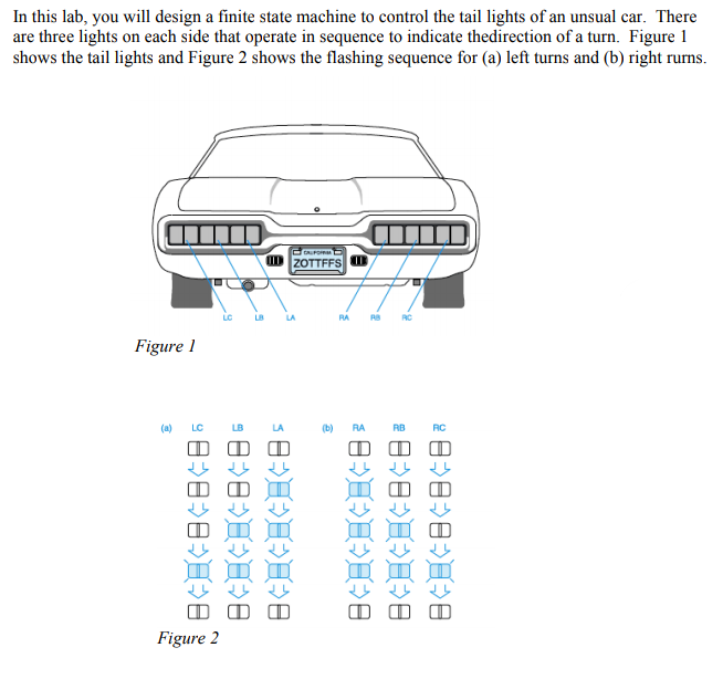
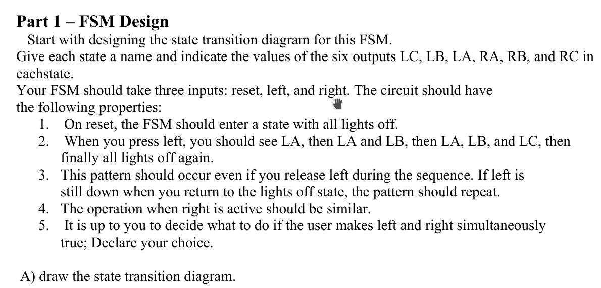
In this lab, you will design a finite state machine to control the tail lights of an unsual car. There are three lights on each side that operate in sequence to indicate thedirection of a turn. Figure 1 shows the tail lights and Figure 2 shows the flashing sequence for (a) left turns and (b) right rurns. ID ZOTTFFS O BARS RC Figure 1 (4) LC LA (b) RA PB RC BEA>B * BB | BEE>B B2B MVB Figure 2 Part 1 - FSM Design Start with designing the state transition diagram for this FSM. Give each state a name and indicate the values of the six outputs LC, LB, LA, RA, RB, and RC in eachstate. Your FSM should take three inputs: reset, left, and right. The circuit should have the following properties: 1. On reset, the FSM should enter a state with all lights off. 2. When you press left, you should see LA, then LA and LB, then LA, LB, and LC, then finally all lights off again. 3. This pattern should occur even if you release left during the sequence. If left is still down when you return to the lights off state, the pattern should repeat. 4. The operation when right is active should be similar. 5. It is up to you to decide what to do if the user makes left and right simultaneously true; Declare your choice. A) draw the state transition diagramStep by Step Solution
There are 3 Steps involved in it
Step: 1

Get Instant Access to Expert-Tailored Solutions
See step-by-step solutions with expert insights and AI powered tools for academic success
Step: 2

Step: 3

Ace Your Homework with AI
Get the answers you need in no time with our AI-driven, step-by-step assistance
Get Started


