Question: In class we learned about the start-finish protocol. We learned that it allowed two state machines, let's call them fsma and fsm_b, to call another
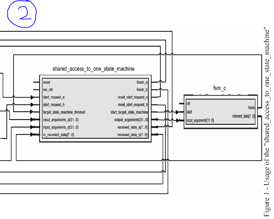
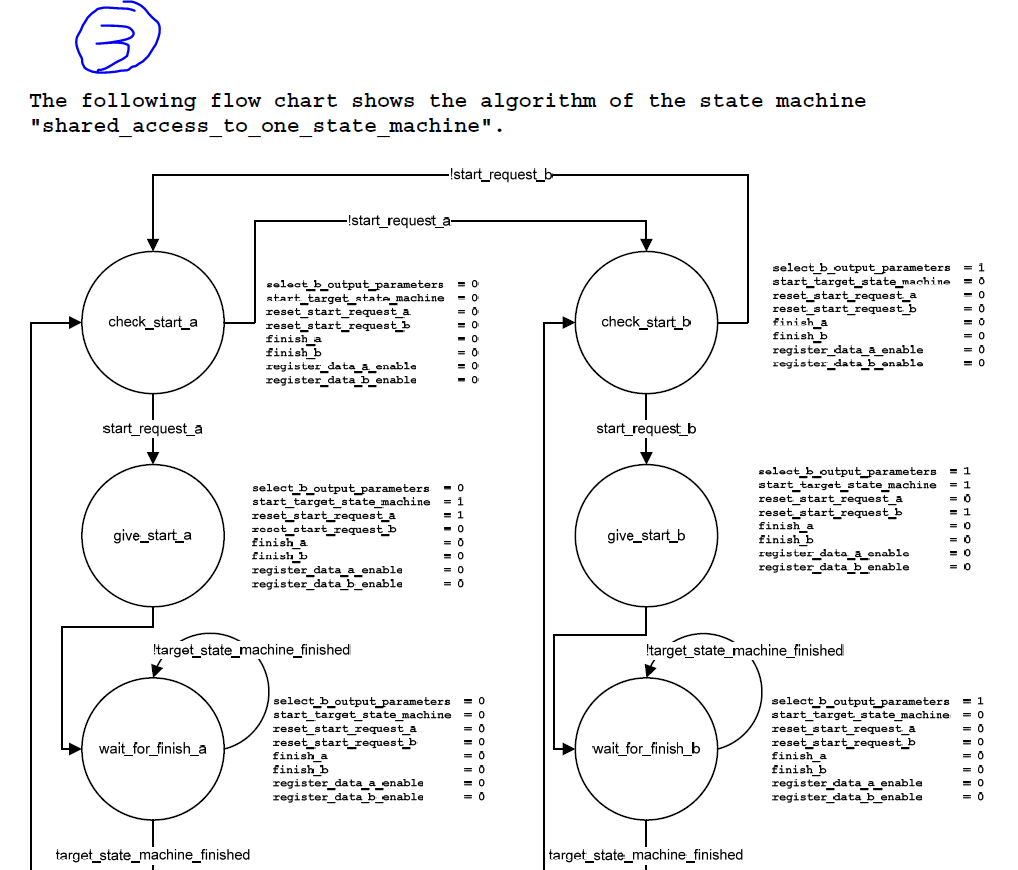
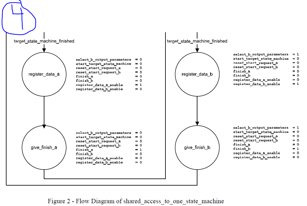
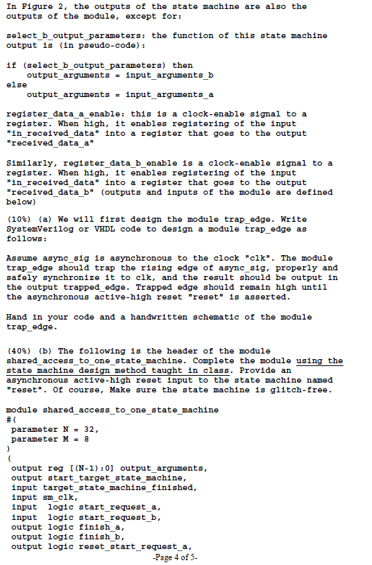
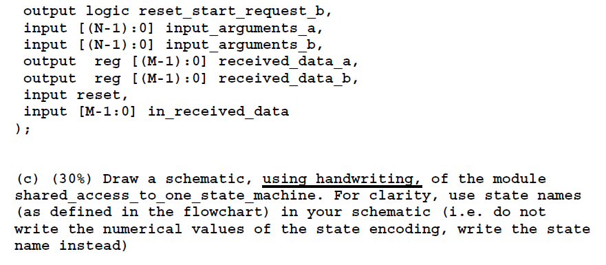
In class we learned about the start-finish protocol. We learned that it allowed two state machines, let's call them fsma and fsm_b, to "call" another state machine, let's call it fsm_c. One disadvantage of the method described in class is that it required that fsma and fsm_b coordinate with each other to avoid trying to "call" Esm_c at the same time. In order to fix this, we can write a state machine that is inserted between Esma and Esm_b, on the one hand, and fsmc, on the other hand. That state machine, that we will call "shared_access_to_one_state_machine", will "trick" fsm_a and fsm_b and make them think that they are the only ones talking to fsm_c. A schematic of the system is shown on the next page. Note that the clocks "clk" and "sm clk" are all connected to the same clock, but those connections are omitted for simplicity in the diagram. The system works as follows. The "trap edge" modules trap the rising edge of the "start" signal, with the output in trapped_edge signifying that a "start" request has been received. The state machine "shared_access_to_one_state_machine" monitors the start requests that are conveyed to it by the trap_edge modules. When a start request is received, "shared_access_to_one_state_machine" first waits for fsm_c to finish (if it is in the middle of completing a "call"), and (once fsmc is free) it then calls fsm_c using the start-finish protocol (it resets the trapped start edge when doing so to make room for the next start request). Arguments to fsm_c are conveyed either from Esma or fsm_b according which is currently calling fsm c. When fsmc finishes, results from fsm_c are registered and passed back from Esm_c to fsm_a or Esm_b according to which of Esma or fsm_b called fsm_c. From the point of view of Esma and fsm_b, they have no idea that between them and Esmc there is another state machine. The only way they might be able to figure that out is if they measure how much time it takes between when they assert "start" to when they get "finish"; if they do that, they may realize it is taking longer than expected. shared_access_to_one_state_machine reset fsm_C finish_a finish_b reset_start_request_a reset_start_request_b start_target_state_machine output_arguments[31..0 received_data_a[7..0) received_data_b[70] sm_clk start_request_a start_request_b target_state_machine_finished input_arguments_a[31.0] input_arguments_b[31.0 in_received_data[70] finish returned_data[7.0 M input_arguments[31.0 Figure 1 - Usage of the "shared access to one state machine" - The following flow chart shows the algorithm of the state machine "shared access to one state machine". !start_request_b- !start_request_a- = check_start_a check_start_b select_b_output_parameters = 0 start_target_state_machine reset_start_request_a reset_start_request_b finish a finish b register_data_a_enable register_data_b_enable select_b_output parameters start_target_state_machine reset_start_request_a reset_start_request_b finish_a finish_b register_data_a_enable register_data_b_enable start_request_a start_request_b select_b_output_parameters - start_target_state_machine reset_start_request_a reset start request_b finish a finish_ register_data_a_enable register_data_b_enable select_b_output parameters = 1 start_target_state_machine reset_start_request_a reset_start_request_b finish a finish_b register_data_a_enable register_data_b_enable give_start_a OOOOHOHH give_start_b !target_state_machine_finished !target_state_machine_finished = wait_for_finish_a select_b_output parameters start_target_state_machine reset start request a reset_start_request_b finish_a finish_b register_data_a_enable register_data_b_enable wait_for_finish_b select_b_output parameters = 1 start_target_state_machine = 0 reset start_request_a reset_start_request_b finish a finish b register_data_a_enable register_data_b_enable target_state_machine_finished target_state_machine_finished target_state_machine_finished target_state_machine_finished select_b_output parameters = start_target_state_machine reset_start_request_a reset_start_request_b finish a finish b register_data_a_enable register_data_b_enable register_data_a select_b_output parameters = 1 start_target_state_machine reset start_request_a reset_start_request_b finish a finish b register_data_a_enable register_data_b_enable OPOOOOOO register_data_b select_b_output_parameters start_target_state_machine reset_start_request_a reset_start_request__ finish a finish_b register_data_a_enable register_data_b_enable select_b_output parameters start_target_state_machine reset_start_request_a reset_start_request b finisha finish_b register_data_a_enable register_data_b_enable give_finish_a OOOOHOOO HOOOOOO give_finish_b Figure 2 - Flow Diagram of shared_access_to_one_state_machine In Figure 2, the outputs of the state machine are also the outputs of the module, except for: select_b_output parameters: the function of this state machine output is (in pseudo-code): 16 (select_b_output parameters) then output_arguments = input_arguments_b else output_arguments = input_arguments a register_data_a_enable: this is a clock-enable sig register. When high, it enables registering of the input "in received data" into a register that goes to the output "received data a" Similarly, register_data_b_enable is a clock-enable signal to a register. When high, it enables registering of the input "in received_data" into a register that goes to the output "received data b" (outputs and inputs of the module are defined below) (108) (a) We will first design the module trap_edge. Write SystemVerilog or VHDL code to design a module trap_edge as follows: Assume async_sig is asynchronous to the clock "elk". The module trap_edge should trap the rising edge of async_sig, properly and safely synchronize it to clk, and the result should be output in the output trapped_edge. Trapped edge should remain high until the asynchronous active-high reset "reset" is asserted. Hand in your code and a handwritten schematic of the module trap_edge. (408) (b) The following is the header of the module shared_access_to_one_state_machine. Complete the module using the state machine design method taught in class. Provide an asynchronous active-high reset input to the state machine named "reset". Of course, Make sure the state machine is glitch-free. module shared access_to_one_state_machine #C parameter N = 32, parameter M = 8 output reg [(N-1):0) output_arguments, output start_target_state_machine, input target_state_machine_finished, input smelk, input logic start_request_a, input logic start_request_b, output logic finish_a, output logic finish_b. output logic reset_start_request_a, - Page 4 of 5. output logic reset_start_request_b, input [(N-1):0] input_arguments_a, input [(N-1):0] input arguments b, output reg [(M-1):0] received data_a, output reg [(M-1):0] received data_b, input reset, input (M-1:0] in received data ); (c) (30%) Draw a schematic, using handwriting of the module shared_access_to_one_state_machine. For clarity, use state names (as defined in the flowchart) in your schematic (i.e. do not write the numerical values of the state encoding, write the state name instead) In class we learned about the start-finish protocol. We learned that it allowed two state machines, let's call them fsma and fsm_b, to "call" another state machine, let's call it fsm_c. One disadvantage of the method described in class is that it required that fsma and fsm_b coordinate with each other to avoid trying to "call" Esm_c at the same time. In order to fix this, we can write a state machine that is inserted between Esma and Esm_b, on the one hand, and fsmc, on the other hand. That state machine, that we will call "shared_access_to_one_state_machine", will "trick" fsm_a and fsm_b and make them think that they are the only ones talking to fsm_c. A schematic of the system is shown on the next page. Note that the clocks "clk" and "sm clk" are all connected to the same clock, but those connections are omitted for simplicity in the diagram. The system works as follows. The "trap edge" modules trap the rising edge of the "start" signal, with the output in trapped_edge signifying that a "start" request has been received. The state machine "shared_access_to_one_state_machine" monitors the start requests that are conveyed to it by the trap_edge modules. When a start request is received, "shared_access_to_one_state_machine" first waits for fsm_c to finish (if it is in the middle of completing a "call"), and (once fsmc is free) it then calls fsm_c using the start-finish protocol (it resets the trapped start edge when doing so to make room for the next start request). Arguments to fsm_c are conveyed either from Esma or fsm_b according which is currently calling fsm c. When fsmc finishes, results from fsm_c are registered and passed back from Esm_c to fsm_a or Esm_b according to which of Esma or fsm_b called fsm_c. From the point of view of Esma and fsm_b, they have no idea that between them and Esmc there is another state machine. The only way they might be able to figure that out is if they measure how much time it takes between when they assert "start" to when they get "finish"; if they do that, they may realize it is taking longer than expected. shared_access_to_one_state_machine reset fsm_C finish_a finish_b reset_start_request_a reset_start_request_b start_target_state_machine output_arguments[31..0 received_data_a[7..0) received_data_b[70] sm_clk start_request_a start_request_b target_state_machine_finished input_arguments_a[31.0] input_arguments_b[31.0 in_received_data[70] finish returned_data[7.0 M input_arguments[31.0 Figure 1 - Usage of the "shared access to one state machine" - The following flow chart shows the algorithm of the state machine "shared access to one state machine". !start_request_b- !start_request_a- = check_start_a check_start_b select_b_output_parameters = 0 start_target_state_machine reset_start_request_a reset_start_request_b finish a finish b register_data_a_enable register_data_b_enable select_b_output parameters start_target_state_machine reset_start_request_a reset_start_request_b finish_a finish_b register_data_a_enable register_data_b_enable start_request_a start_request_b select_b_output_parameters - start_target_state_machine reset_start_request_a reset start request_b finish a finish_ register_data_a_enable register_data_b_enable select_b_output parameters = 1 start_target_state_machine reset_start_request_a reset_start_request_b finish a finish_b register_data_a_enable register_data_b_enable give_start_a OOOOHOHH give_start_b !target_state_machine_finished !target_state_machine_finished = wait_for_finish_a select_b_output parameters start_target_state_machine reset start request a reset_start_request_b finish_a finish_b register_data_a_enable register_data_b_enable wait_for_finish_b select_b_output parameters = 1 start_target_state_machine = 0 reset start_request_a reset_start_request_b finish a finish b register_data_a_enable register_data_b_enable target_state_machine_finished target_state_machine_finished target_state_machine_finished target_state_machine_finished select_b_output parameters = start_target_state_machine reset_start_request_a reset_start_request_b finish a finish b register_data_a_enable register_data_b_enable register_data_a select_b_output parameters = 1 start_target_state_machine reset start_request_a reset_start_request_b finish a finish b register_data_a_enable register_data_b_enable OPOOOOOO register_data_b select_b_output_parameters start_target_state_machine reset_start_request_a reset_start_request__ finish a finish_b register_data_a_enable register_data_b_enable select_b_output parameters start_target_state_machine reset_start_request_a reset_start_request b finisha finish_b register_data_a_enable register_data_b_enable give_finish_a OOOOHOOO HOOOOOO give_finish_b Figure 2 - Flow Diagram of shared_access_to_one_state_machine In Figure 2, the outputs of the state machine are also the outputs of the module, except for: select_b_output parameters: the function of this state machine output is (in pseudo-code): 16 (select_b_output parameters) then output_arguments = input_arguments_b else output_arguments = input_arguments a register_data_a_enable: this is a clock-enable sig register. When high, it enables registering of the input "in received data" into a register that goes to the output "received data a" Similarly, register_data_b_enable is a clock-enable signal to a register. When high, it enables registering of the input "in received_data" into a register that goes to the output "received data b" (outputs and inputs of the module are defined below) (108) (a) We will first design the module trap_edge. Write SystemVerilog or VHDL code to design a module trap_edge as follows: Assume async_sig is asynchronous to the clock "elk". The module trap_edge should trap the rising edge of async_sig, properly and safely synchronize it to clk, and the result should be output in the output trapped_edge. Trapped edge should remain high until the asynchronous active-high reset "reset" is asserted. Hand in your code and a handwritten schematic of the module trap_edge. (408) (b) The following is the header of the module shared_access_to_one_state_machine. Complete the module using the state machine design method taught in class. Provide an asynchronous active-high reset input to the state machine named "reset". Of course, Make sure the state machine is glitch-free. module shared access_to_one_state_machine #C parameter N = 32, parameter M = 8 output reg [(N-1):0) output_arguments, output start_target_state_machine, input target_state_machine_finished, input smelk, input logic start_request_a, input logic start_request_b, output logic finish_a, output logic finish_b. output logic reset_start_request_a, - Page 4 of 5. output logic reset_start_request_b, input [(N-1):0] input_arguments_a, input [(N-1):0] input arguments b, output reg [(M-1):0] received data_a, output reg [(M-1):0] received data_b, input reset, input (M-1:0] in received data ); (c) (30%) Draw a schematic, using handwriting of the module shared_access_to_one_state_machine. For clarity, use state names (as defined in the flowchart) in your schematic (i.e. do not write the numerical values of the state encoding, write the state name instead)
Step by Step Solution
There are 3 Steps involved in it

Get step-by-step solutions from verified subject matter experts


