IN JAVA!!!!
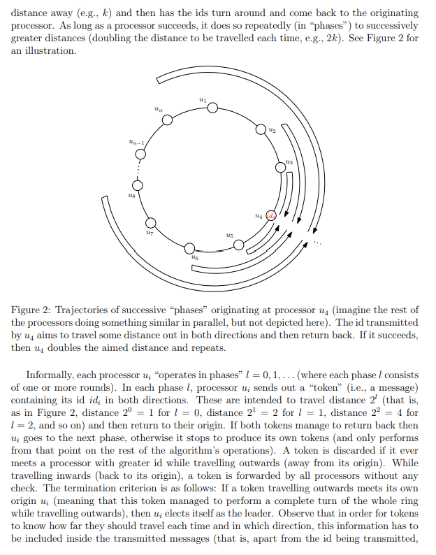
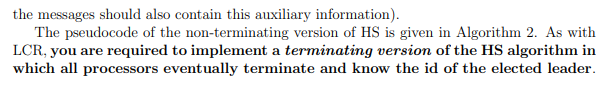
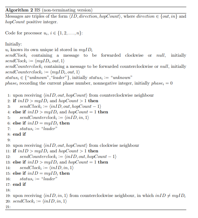
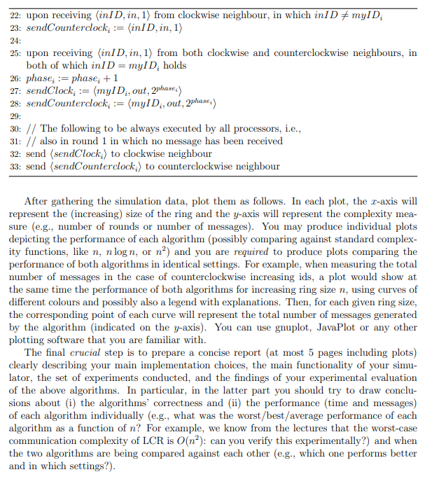
3.2 Implementing the HS Algorithm-30% of the assignment mark Next, you are required to implement another algorithm for leader election on a ring, known as the HS algorithm. As LCR, HS also elects the processor with the maximum id. The main difference is that HS instead of trying to send ids all the way around in one direction (which is what LCR does), it has every processor trying to send its id in both directions some distance away (e.g., k) and then has the ids turn around and come back to the originating processor. As long as a processor succeeds, it does so repeatedly (in "phases) to successively greater distances (doubling the distance to be travelled each time, e.g., 2k). See Figure 2 for an illustration. 113 ts Figure 2: Trajectories of successive phases" originating at processor us (imagine the rest of the processors doing something similar in parallel, but not depicted here). The id transmitted by uy aims to travel some distance out in both directions and then return back. If it succeeds, then u, doubles the aimed distance and repeats. Informally, each processor u; operates in phases I = 0,1,... (where each phase I consists of one or more rounds). In each phase 1, processor ui sends out a "token" (i.e., a message) containing its id id; in both directions. These are intended to travel distance 2 (that is, as in Figure 2, distance 2 = 1 for 1 = 0, distance 21 = 2 for 1 = 1, distance 22 = 4 for 1 = 2, and so on) and then return to their origin. If both tokens manage to return back then Ui goes to the next phase, otherwise it stops to produce its own tokens (and only performs from that point on the rest of the algorithm's operations). A token is discarded if it ever meets a processor with greater id while travelling outwards away from its origin). While travelling inwards (back to its origin), a token is forwarded by all processors without any check. The termination criterion is as follows: If a token travelling outwards meets its own origin ui (meaning that this token managed to perform a complete turn of the whole ring while travelling outwards), then u elects itself as the leader. Observe that in order for tokens to know how far they should travel each time and in which direction, this information has to be included inside the transmitted messages (that is, apart from the id being transmitted, the messages should also contain this auxiliary information). The pseudocode of the non-terminating version of HS is given in Algorithm 2. As with LCR, you are required to implement a terminating version of the HS algorithm in which all processors eventually terminate and know the id of the elected leader. Algorithm 2 HS (non-terminating version) Messages are triples of the form (ID, direction, hopCount), where direction {out, in} and hopCount positive integer. Code for processor Ui, i {1, 2, ..., n}: Initially: U; knows its own unique id stored in myID sendClocki containing a message to be forwarded clockwise or null, initially sendClock; := (myl Di, out, 1) sendCounterclock; containing a message to be forwarded counterclockwise or null, initially sendCounterclock; := (myl Di, out, 1) status: {"unknown","leader"}, initially status; := "unknown" phase; recording the current phase number, nonnegative integer, initially phase; = 0 3: 5: 7: 1: upon receiving (inID, out, hopCount) from counterclockwise neighbour 2: if ini D > myID; and hopCount > 1 then sendClock; := (inID, out, hopCount - 1) 4: else if inID > myID; and hopCount = 1 then sendCounterclock; := (in D, in, 1) 6: else if in D = myl D, then status: := "leader" 8: end if 9: 10: upon receiving (inID, out, hopCount) from clockwise neighbour 11: if in D > myID; and hopCount > 1 then sendCounterclock; := (inID, out, hopCount - 1) 13: else if inID > myID, and hopCount = 1 then 14: sendClock; := (inID, in, 1) 15: else if inID = mylD; then status; := "leader" 17: end if 12: 16: 18: 19: upon receiving (inID, in, 1) from counterclockwise neighbour, in which inl D + myID 20: sendClock; := (inID, in, 1) 21: 22: upon receiving in D, in, 1) from clockwise neighbour, in which inID #myID 23: sendCounterclock; := (inID, in, 1) 24: 25: upon receiving (inID, in, 1) from both clockwise and counterclockwise neighbours, in both of which inID = myID, holds 26: phase; := phase; +1 27: sendClock; := (myl D, out, 2phase :) 28: sendCounterclock; := (myID;, out, 2phase:) 29: 30: // The following to be always executed by all processors, i.e., 31: // also in round 1 in which no message has been received 32: send (sendClock) to clockwise neighbour 33: send (sendCounterclock;) to counterclockwise neighbour After gathering the simulation data, plot them as follows. In each plot, the c-axis will represent the increasing) size of the ring and the y-axis will represent the complexity mea- sure (e.g., number of rounds or number of messages). You may produce individual plots depicting the performance of each algorithm (possibly comparing against standard complex- ity functions, like n, n logn, or n) and you are required to produce plots comparing the performance of both algorithms in identical settings. For example, when measuring the total number of messages in the case of counterclockwise increasing ids, a plot would show at the same time the performance of both algorithms for increasing ring size n, using curves of different colours and possibly also a legend with explanations. Then, for each given ring size, the corresponding point of each curve will represent the total number of messages generated by the algorithm (indicated on the y-axis). You can use gnuplot, JavaPlot or any other plotting software that you are familiar with. The final crucial step is to prepare a concise report (at most 5 pages including plots) clearly describing your main implementation choices, the main functionality of your simu- lator, the set of experiments conducted, and the findings of your experimental evaluation of the above algorithms. In particular, in the latter part you should try to draw conclu- sions about (i) the algorithms' correctness and (ii) the performance (time and messages) of each algorithm individually (e.g., what was the worst/best/average performance of each algorithm as a function of n? For example, we know from the lectures that the worst-case communication complexity of LCR is O(n): can you verify this experimentally ?) and when the two algorithms are being compared against each other (e.g., which one performs better and in which settings?)