

Answered step by step
Verified Expert Solution
Question
1 Approved Answer
in multisim 1. Consider the circuit shown in Figure 12.34(a). Replace the input signal source with an ideal signal voltage source. Using a computer simulation,
in multisim
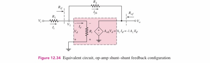
1. Consider the circuit shown in Figure 12.34(a). Replace the input signal source with an ideal signal voltage source. Using a computer simulation, investigate the small-signal voltage gain, input resistance Rif, and output resistance Rof as a function of the feedback resistance RF. R Ris 17 RO R V; - www w R ALV=W.Ve=-1A,1! que se ve Figure 12.34 Equivalent circuit, op-amp shunt-shunt feedback configuration 1. Consider the circuit shown in Figure 12.34(a). Replace the input signal source with an ideal signal voltage source. Using a computer simulation, investigate the small-signal voltage gain, input resistance Rif, and output resistance Rof as a function of the feedback resistance RF. R Ris 17 RO R V; - www w R ALV=W.Ve=-1A,1! que se ve Figure 12.34 Equivalent circuit, op-amp shunt-shunt feedback configuration Step by Step Solution
There are 3 Steps involved in it
Step: 1

Get Instant Access to Expert-Tailored Solutions
See step-by-step solutions with expert insights and AI powered tools for academic success
Step: 2

Step: 3
Ace Your Homework with AI
Get the answers you need in no time with our AI-driven, step-by-step assistance
Get Started
Marketing Audit Reports Get An Extensive List Of 130 Marketing Audit Reports
Authors: Jack Chalow
1st Edition
B0BQXYKYZJ, 979-8371063076