Answered step by step
Verified Expert Solution
Question
1 Approved Answer
In Powermill program, open the powerdrill.dgk file in the Examples folder and do the following. 1-) Create a block with dimensions X = 555 mm,
In Powermill program, open the powerdrill.dgk file in the Examples folder and do the following.
1-) Create a block with dimensions X = 555 mm, Y = 355 mm and Z = 55 mm.
-Reposition the working plane so that the middle of the part in the X and Y elsenals is at the top point of the part in the Z axis.
-Set the spindle speed to be 1255 rpm, Cutting feed 955 mm / min, Approach feed 755 mm / min and Transition feed 9555 mm / min.
2-) To remove chips from the block with a tool with a diameter of 35 mm and an end radius of 6 mm, calculate the tool path by taking the following items carefully.
-Calculate the side step value.
Set the vertical pitch to 2 mm.
- For the finishing process, leave a working margin of 0.5 mm on the side (vertiical) surfaces and 0.3 mm on the flat (horizontal) surfaces.
- Set the cutting direction in both directions only on the model surface and do not allow the cutting direction to be maintained.
3-) Create a new toolpath on the tool path you created in the 2nd Question with a tool with a diameter of 8 mm and a tip radius of 2 mm.
-Calculate the side step value.
-Don't let the team center get outside of the block.
- Ensure that tool paths shorter than 12 mm are connected with a circular spring.
-Create a new toolpath on the toolpath you just created with the end radius tool with diameter 4, end radius 1mm.
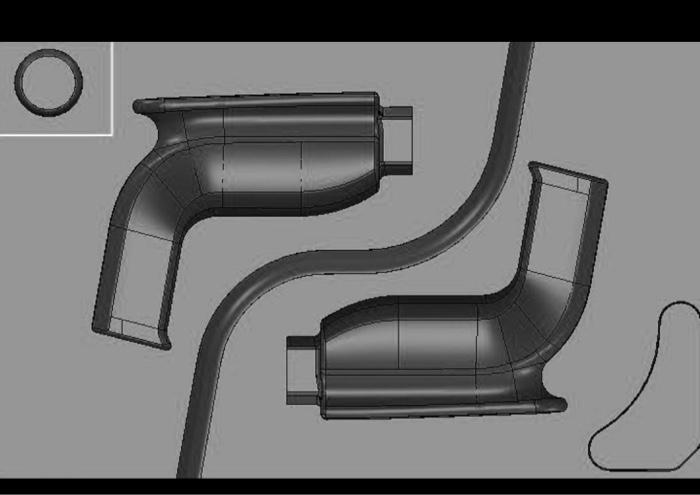
4-) By creating a rectangular border on the upper left corner of the model as shown in the figure, write the tool path in this border according to the Vertical and Horizontal Finishing strategy with a spherical tool with a diameter of 5 mm.
- Set the vertical step value of the zones perpendicular to 25 so that the step end height is 0.3 mm, and the side step value of the horizontal zones is 0.1 mm.
- Scan the tool path of horizontal (Shallow) regions.
- Make sure that scanning takes place in both directions.
- Overlap the vertical and horizontal tool paths to be formed by 3 mm.
5-) By creating a border, write a tool path with Fixed Z Finishing strategies for places steeper than 32, Scan Finishing strategies for shallower places than 32.
- Use a ball tool with a diameter of 4 mm.
- Make sure that vertical areas are processed layer by layer.
- Make sure that the toolpaths that cut through in Scan to Finish do not close (patch) with steep toolpaths.
- Ensure that the toolpaths opened on scan finish are deleted.

Picture for part 4
Step by Step Solution
There are 3 Steps involved in it
Step: 1

Get Instant Access to Expert-Tailored Solutions
See step-by-step solutions with expert insights and AI powered tools for academic success
Step: 2

Step: 3

Ace Your Homework with AI
Get the answers you need in no time with our AI-driven, step-by-step assistance
Get Started


