

Question
In the above diagram, add diagonal lines to indicate the size of each of the lines coming into and going out of each logic element.
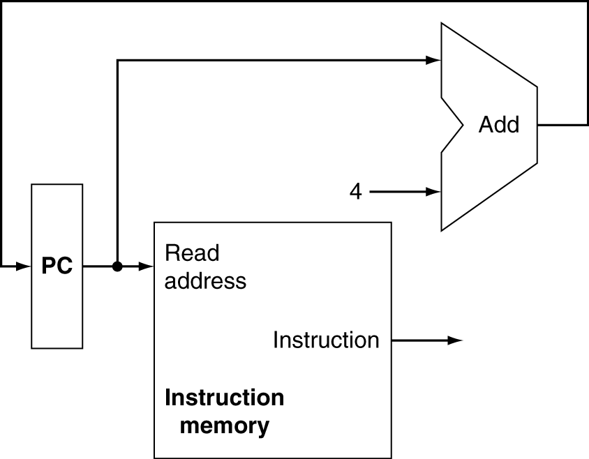
In the above diagram, add diagonal lines to indicate the size of each of the lines coming into and going out of each logic element.
To continue in this exercise we will need to have one more concept down. This is the idea that we may want more than one input in general to a particular logic component. For example in the above diagram we may want to sometimes get a new program counter that is just the next instruction (hence the add 4 to the current program counter) or if the instruction is a branch or jump we will want to get some information from the instruction to change to the new program counter. When we want two different inputs, we need to use a multiplexor to change between the two rather than have two outputs (old PC and instruction) both going into the same input (new PC).
The diagram below shows an overview of the whole processor design we will be modifying.

Redo the diagram inserting multiplexors where needed.
Now that you have a new diagram with multiplexors, you will be focusing on elaborating on each section of the overview diagram to account for different parts of the execution of the machine for different instructions. To make sure that you understand the overview diagram, answer the following questions with respect to it.
What bits of the instruction will be sent to the second adder in the circuit computing the new PC why?
What bits of the instruction will be going into each of the Register # inputs of the Register file in the center of the machine?
For what kind of instruction will the output of the data memory be going into the input of the register file? Explain.
Now add to your overview picture, an oval for control showing lines coming in and lines going out to control the multiplexors. Label each line going into a multiplexor with a descriptive word to describe what control we want selecting the multiplexor input.
Add Read address PC Instruction Instruction memory Add Read address PC Instruction Instruction memoryStep by Step Solution
There are 3 Steps involved in it
Step: 1

Get Instant Access to Expert-Tailored Solutions
See step-by-step solutions with expert insights and AI powered tools for academic success
Step: 2

Step: 3
Ace Your Homework with AI
Get the answers you need in no time with our AI-driven, step-by-step assistance
Get Started
Upgrading Oracle Databases Oracle Database New Features
Authors: Charles Kim, Gary Gordhamer, Sean Scott
1st Edition
B0BL12WFP6, 979-8359657501