

Answered step by step
Verified Expert Solution
Question
1 Approved Answer
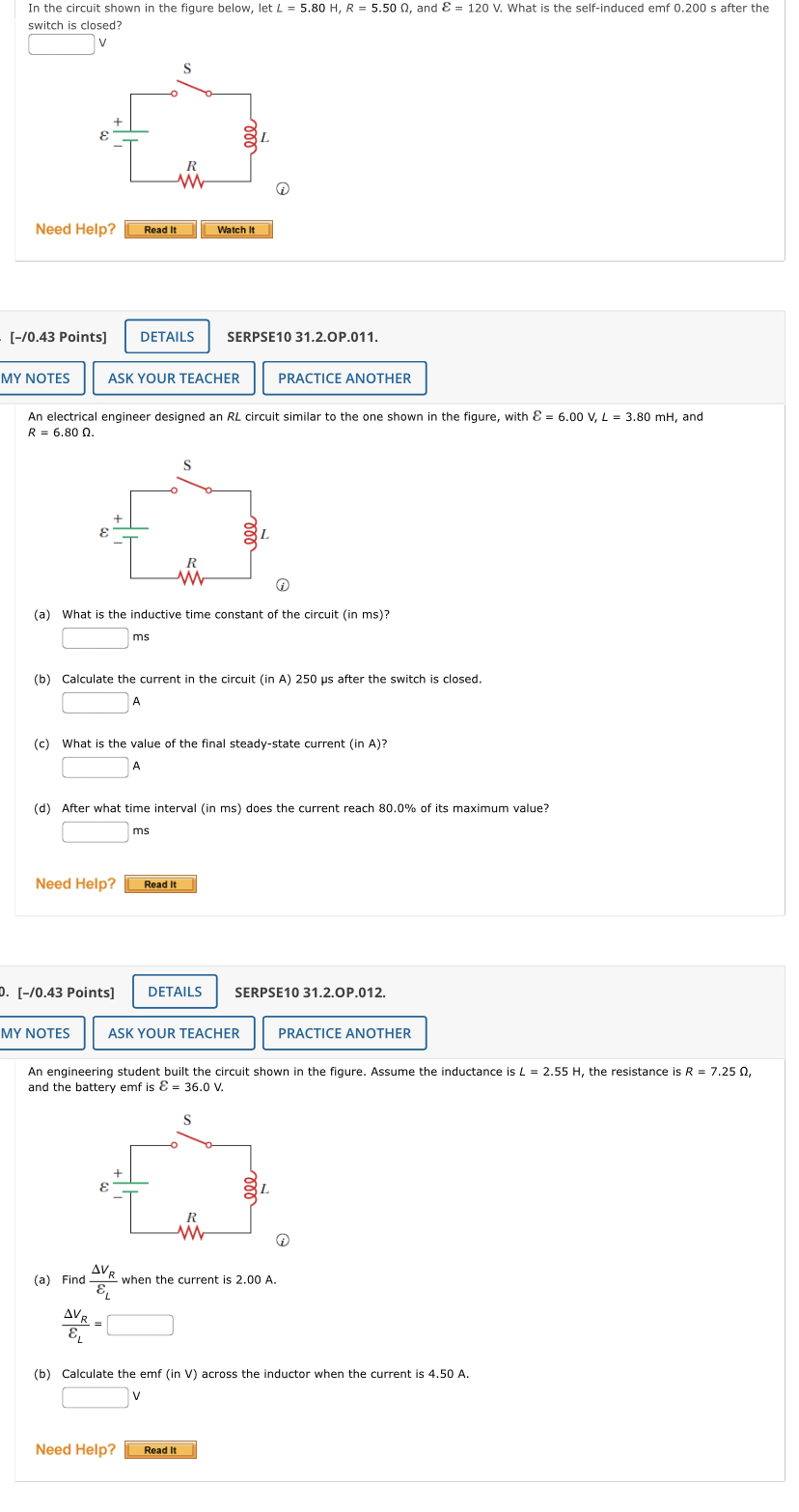
In the circuit shown in the figure below, let L = 5.80 H, R = 5.50 0, and & = 120 V. What is the
Step by Step Solution
There are 3 Steps involved in it
Step: 1

Get Instant Access to Expert-Tailored Solutions
See step-by-step solutions with expert insights and AI powered tools for academic success
Step: 2

Step: 3
Ace Your Homework with AI
Get the answers you need in no time with our AI-driven, step-by-step assistance
Get Started
Statistical Field Theory For Neural Networks
Authors: Moritz Helias, David Dahmen
1st Edition
978-3030464431