Question: In this lab, we will use the inverse kinematics to identify two functions to generate an animation of a two-link robot. As mentioned in


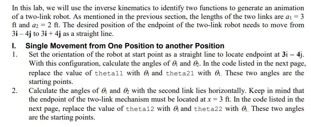
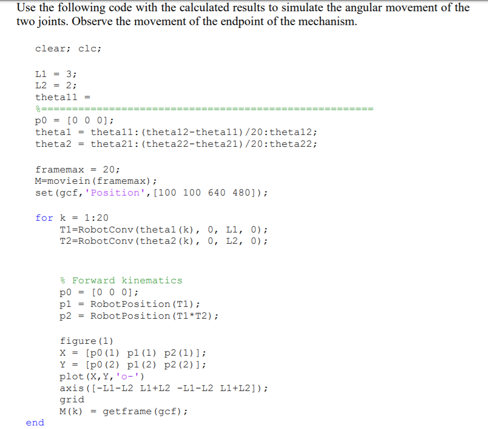
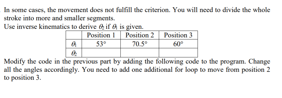
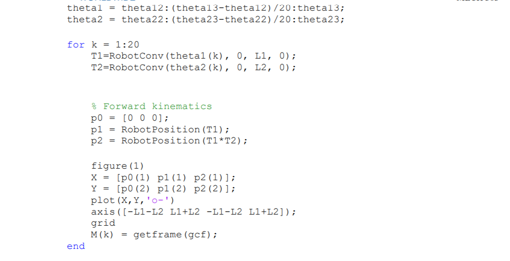
In this lab, we will use the inverse kinematics to identify two functions to generate an animation of a two-link robot. As mentioned in the previous section, the lengths of the two links are a = 3 ft and a2 = 2 ft. The desired position of the endpoint of the two-link robot needs to move from 3i 4j to 3i + 4j as a straight line. I. Single Movement from One Position to another Position 1. Set the orientation of the robot at start point as a straight line to locate endpoint at 3i 4j. With this configuration, calculate the angles of & and . In the code listed in the next page, replace the value of thetall with and theta21 with . These two angles are the starting points. Calculate the angles of and 2 with the second link lies horizontally. Keep in mind that the endpoint of the two-link mechanism must be located at x = 3 ft. In the code listed in the next page, replace the value of theta12 with and theta22 with . These two angles are the starting points. 2. Use the following code with the calculated results to simulate the angular movement of the two joints. Observe the movement of the endpoint of the mechanism. clear; clc; L1 = 3; L2 = 2; thetall = %= po = [0 0 0]; thetal = theta2 = framemax = 20; M=moviein (framemax); set (gcf, 'Position', [100 100 640 480]); for k = 1:20 end thetall: (theta12-thetall) /20: theta12; theta21: (theta22-theta21) /20: theta22; T1=Robot Conv (thetal (k), 0, L1, 0); T2=RobotConv (theta2 (k), 0, L2, 0); % Forward kinematics po [0 0 0]; pl Robot Position (T1); p2 = Robot Position (T1*T2); = = figure (1) X= [p0 (1) p1 (1) p2 (1) ]; Y = [p0 (2) p1 (2) p2 (2) ]; plot (X, Y, '0- ') axis ([-L1-L2 L1+L2 -L1-L2 L1+L2]); grid M(K) = getframe (gcf); In some cases, the movement does not fulfill the criterion. You will need to divide the whole stroke into more and smaller segments. Use inverse kinematics to derive if Position 1 53 0 is given. Position 2 Position 3 70.5 60 Modify the code in the previous part by adding the following code to the program. Change all the angles accordingly. You need to add one additional for loop to move from position 2 to position 3. thetal = thetal2: (thetal3-thetal2)/20: theta13; theta2 = theta22: (theta23-theta22) /20: theta23; for k=1:20 end T1=Robot Conv (thetal (k), 0, L1, 0); T2=RobotConv (theta2 (k), 0, L2, 0); & Forward kinematics p0 = [0 0 0]; pl = Robot Position (T1); p2 = Robot Position (T1*T2); figure (1) X = [p0 (1) p1 (1) p2 (1) 1; Y [p0 (2) p1 (2) p2 (2) ] ; plot (X, Y, '0-') axis ([-L1-L2 L1+L2 -L1-L2 L1+L2]); grid M(K) = getframe (gcf); In this part, you need to plan the trajectory from 3i 4j to 3i + 4j as a straight line. Generate a table with all the planned angles. Write the code and simulate the movement of the two-link mechanism.
Step by Step Solution
3.44 Rating (160 Votes )
There are 3 Steps involved in it
To solve this problem we will use inverse kinematics to find the joint angles that position the twolink robot at specific points Heres how to approach ... View full answer

Get step-by-step solutions from verified subject matter experts


