Answered step by step
Verified Expert Solution
Question
1 Approved Answer
In this lab, you will setup the OSPF routing for the network shown below. R2 GO/0 PC-B 0/0/05 0/0/05 R1 GO/0 PC-A So/0/1 SO/0/1
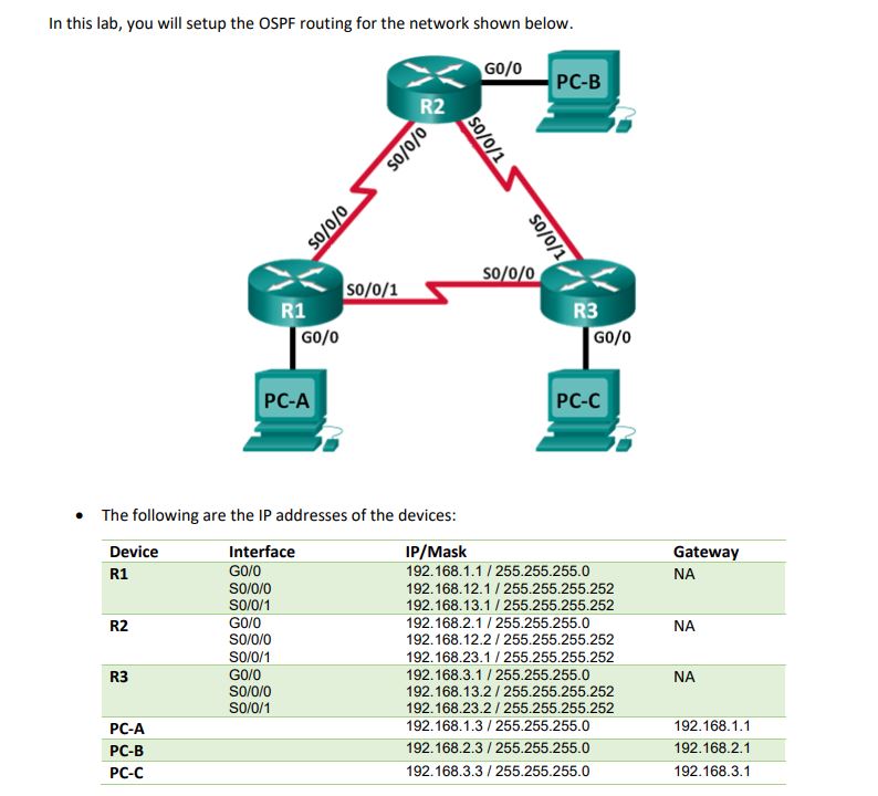
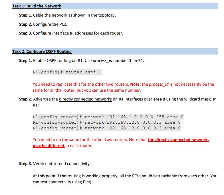
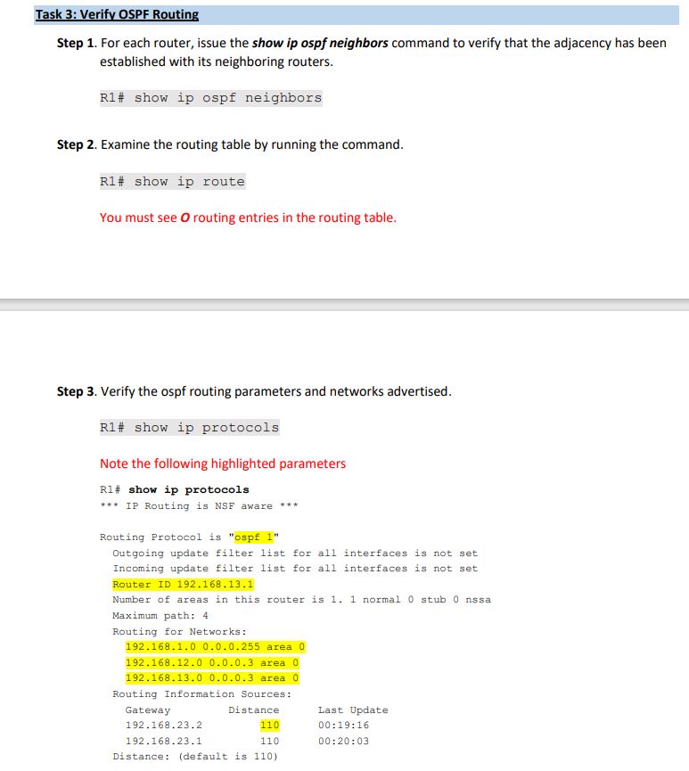
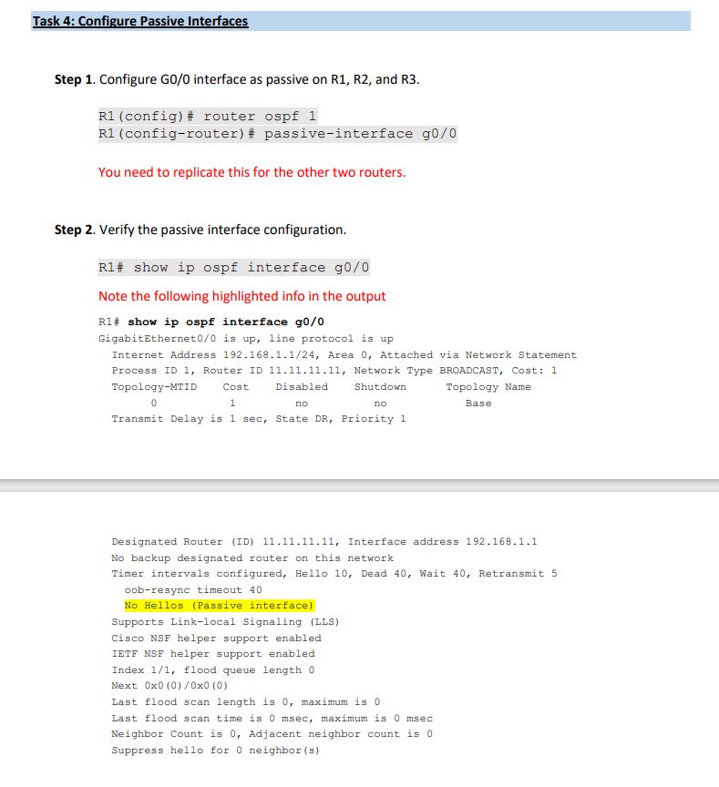
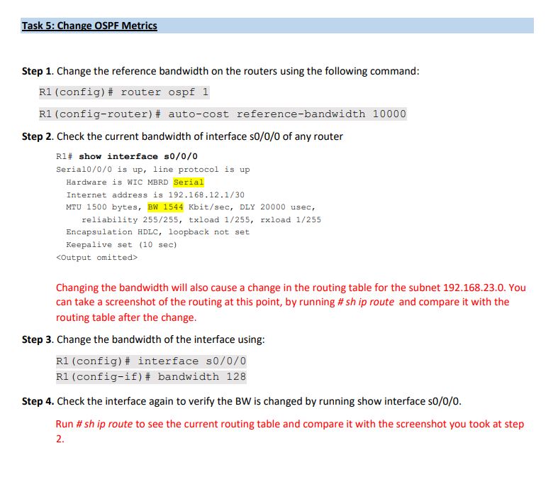
In this lab, you will setup the OSPF routing for the network shown below. R2 GO/0 PC-B 0/0/05 0/0/05 R1 GO/0 PC-A So/0/1 SO/0/1 S0/0/1 S0/0/0 The following are the IP addresses of the devices: Device R1 Interface GO/0 S0/0/0 S0/0/1 R2 GO/0 S0/0/0 S0/0/1 33 R3 GO/0 S0/0/0 S0/0/1 PC-A PC-B PC-C R3 GO/0 PC-C IP/Mask Gateway 192.168.1.1/255.255.255.0 NA 192.168.12.1/255.255.255.252 192.168.13.1/255.255.255.252 192.168.2.1/255.255.255.0 NA 192.168.12.2/255.255.255.252 192.168.23.1/255.255.255.252 192.168.3.1/255.255.255.0 192.168.13.2/255.255.255.252 192.168.23.2/255.255.255.252 192.168.1.3/255.255.255.0 192.168.2.3/255.255.255.0 NA 192.168.1.1 192.168.2.1 192.168.3.3/255.255.255.0 192.168.3.1 Task 1: Build the Network Step 1. Cable the network as shown in the topology. Step 2. Configure the PCs. Step 3. Configure interface IP addresses for each router. Task 2: Configure OSPF Routing Step 1. Enable OSPF routing on R1. Use process_id number 1. In R1: R1 (config)# router ospf 1 You need to replicate this for the other two routers. Note: the process_id is not necessarily be the same for all the router, but you can use the same number. Step 2. Advertise the directly connected networks on R1 interfaces over area 0 using the wildcard mask. In R1: R1 (config-router) #23 network 192.168.1.0 0.0.0.255 area 0 R1 (config-router) #23 network 192.168.12.0 0.0.0.3 area 0 R1 (config-router) %23 network 192.168.13.0 0.0.0.3 area 0 You need to do the same for the other two routers. Note that the directly connected networks may be different in each router. Step 3. Verify end-to-end connectivity. At this point if the routing is working properly, all the PCs should be reachable from each other. You can test connectivity using Ping. Task 3: Verify OSPF Routing Step 1. For each router, issue the show ip ospf neighbors command to verify that the adjacency has been established with its neighboring routers. R1# show ip ospf neighbors Step 2. Examine the routing table by running the command. R1# show ip route You must see O routing entries in the routing table. Step 3. Verify the ospf routing parameters and networks advertised. R1# show ip protocols Note the following highlighted parameters R1% show ip protocols *** IP Routing is NSF aware *** Routing Protocol is "ospf 1" Outgoing update filter list for all interfaces is not set Incoming update filter list for all interfaces is not set Router ID 192.168.13.1 Number of areas in this router is 1. 1 normal 0 stub 0 nssa Maximum path: 4 Routing for Networks: 192.168.1.0 0.0.0.255 area 0 192.168.12.0 0.0.0.3 area 0 192.168.13.0 0.0.0.3 area 0. Routing Information Sources: Gateway Distance Last Update 192.168.23.2 110 00:19:161 192.168.23.1 110 00:20:03 Distance: (default is 110) Task 4: Configure Passive Interfaces Step 1. Configure G0/0 interface as passive on R1, R2, and R3. R1 (config)# router ospf 1 R1 (config-router) # passive-interface g0/0 You need to replicate this for the other two routers. Step 2. Verify the passive interface configuration. R1# show ip ospf interface g0/0 Note the following highlighted info in the output R1% show ip ospf interface g0/0 GigabitEthernet0/0 is up, line protocol is up Internet Address 192.168.1.1/24, Area 0, Attached via Network Statement Process ID 1, Router ID 11.11.11.11, Network Type BROADCAST, Cost: 1 Topology-MTID 0 Cost 1 Disabled Shutdown Topology Name no no Base Transmit Delay is 1 sec, State DR, Priority 1 Designated Router (ID) 11.11.11.11, Interface address 192.168.1.1 No backup designated router on this network Timer intervals configured, Hello 10, Dead 40, Wait 40, Retransmit 5 oob-resync timeout 40 No Hellos (Passive interface) Supports Link-local Signaling (LLS). Cisco NSF helper support enabled IETF NSF helper support enabled Index 1/1, flood queue length 0 Next 0x0 (0)/0x0 (0) Last flood scan length is 0, maximum is 0 Last flood scan time is 0 msec, maximum is 0 msec Neighbor Count is 0, Adjacent neighbor count is 0 Suppress hello for 0 neighbor (s) Task 5: Change OSPF Metrics Step 1. Change the reference bandwidth on the routers using the following command: R1 (config)# router ospf 1 R1 (config-router) #23 auto-cost reference-bandwidth 10000 Step 2. Check the current bandwidth of interface s0/0/0 of any router R1# show interface 0/0/0 Serial0/0/0 is up, line protocol is up Hardware is WIC MBRD Serial Internet address is 192.168.12.1/30 MTU 1500 bytes, BW 1544 Kbit/sec, DLY 20000 usec, reliability 255/255, txload 1/255, rxload 1/255 Encapsulation HDLC, loopback not set Keepalive set (10 sec). Changing the bandwidth will also cause a change in the routing table for the subnet 192.168.23.0. You can take a screenshot of the routing at this point, by running #sh ip route and compare it with the routing table after the change. Step 3. Change the bandwidth of the interface using: R1 (config)# interface s0/0/0 R1 (config-if) %23 bandwidth 128 Step 4. Check the interface again to verify the BW is changed by running show interface S0/0/0. Run #sh ip route to see the current routing table and compare it with the screenshot you took at step 2.
Step by Step Solution
There are 3 Steps involved in it
Step: 1

Get Instant Access to Expert-Tailored Solutions
See step-by-step solutions with expert insights and AI powered tools for academic success
Step: 2

Step: 3

Ace Your Homework with AI
Get the answers you need in no time with our AI-driven, step-by-step assistance
Get Started


