

Answered step by step
Verified Expert Solution
Question
1 Approved Answer
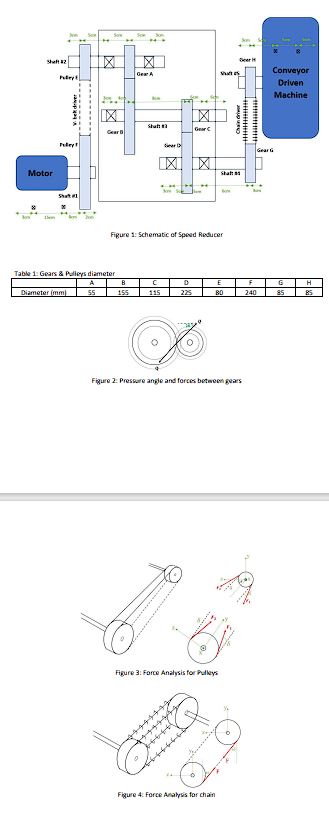
In this project, the objective is to create a speed reduction system, which is utilized to decrease rotational speed while enhancing output torque. Speed reducers
In this project, the objective is to create a speed reduction system, which is utilized to decrease
rotational speed while enhancing output torque. Speed reducers find applications across various
industries, including transportation, construction, mechanical processing, and others. They
typically consist of multiple shafts and gears. The primary purpose of a speed reducer is to regulate
both speed and output torque. Fig. illustrates a typical speed reducer, comprising an electric
motor, shafts, gears, pulleys, bearings, a belt, and a chain. The dimensions are detailed in Figure
and the gear diameters are provided in Table The pressure angle between the gears is
degrees Fig The force analysis of the pulleys is depicted in Fig. leading to the derivation of
two pulley formulas F F and FF with delta degrees Additionally,
the force analysis of the chain is presented in Fig where one side of the chain experiences zero
force The electric motor has a power rating of kW and operates at an angular speed of
rpm Furthermore, the power transfer between Gear C and Gear D accounts for of the total
power.
You are asked to complete the following design tasks:
a Choose a motor for speed reducer from catalogue.
b Draw the free body diagram FBD of each shaft.
c Calculate forces exerted on each bearing.
d Draw shear force and momentum graph for each shaft.
e Calculate rating life for each bearing the bearings work for years and hours per day
Calculate load capacity of each bearing for ball bearing and roller bearing.
f Choose material CK for shafts and based on momentums obtained from previous parts,
compute the diameters of each step of the shaft Factor of safety n is Dr rd
r
g Choose bearings from SKF bearing catalogue.
h Draw a technical drawing for each shaft.
i Draw the whole equipment in CAD Software as D
Step by Step Solution
There are 3 Steps involved in it
Step: 1

Get Instant Access to Expert-Tailored Solutions
See step-by-step solutions with expert insights and AI powered tools for academic success
Step: 2

Step: 3
Ace Your Homework with AI
Get the answers you need in no time with our AI-driven, step-by-step assistance
Get Started
Fundamentals Of Hydraulic Engineering Systems
Authors: Robert J. Houghtalen, A. Osman H. Akan, Ned H. C. Hwang
4th Edition
136016383, 978-0136016380