

Question
In your training kit, there is a combinational circuit that converts a decimal digit represented in 8-4-2-1 BCD system into an appropriate code for the
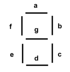
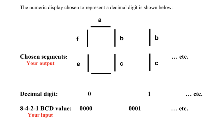
In your training kit, there is a combinational circuit that converts a decimal digit represented in 8-4-2-1 BCD system into an appropriate code for the selection of segments in a seven-segment display, in order to display the decimal digit in familiar form. The outputs of the circuit (a,b,c,d,e,f,g) select the corresponding segments in the display as shown below.
In this part, you will extend the circuit you have built in part 1 to display the output of the Adder/subtractor to three of the 7-segment displays on your digital kit.
Specifically, the first seven-segment display shall be dedicated to display the sign of the result. When, your result is positive, this seven-segment shall display zero. And, when your result is negative, it shall display one.
The second and the third seven-segment displays are dedicated to show the value of your results from part1. That is if the result from part 1 came from adding 3 to 5, then your answer is 8. So, the second seven-segment shall display zero, and the third seven-segment shall display 8. On the other hand, if you added 7 to 6, your answer will be 13. So, your second seven-segment display shall display 1, and your third seven-segment shall display 3. (Hint: for this case, you can use a comparator that compares the result obtained from part 1, only when an addition operation is executed, and the value 9, if the result is larger than 9, then subtract from it 10, then display the obtained value from the former subtraction on the second seven-segment and display one at the third seven-segment display).
Furthermore, if you perform 3 4, then your answer will be -1 and it isexpressed in 2s complement at the output of part 1 as (1111) 2s complement . In this case, your first seven-segment shall display the sign which is 1, and the second seven-segment shall display 0, and the third seven-segment shall display 1 (that is, you have to implement another circuit that finds the 2scomplement of the result obtained from part 1 in case you have a negative result)
In designing this circuit, you are allowed to use 4-bit magnitude comparators (74LS85), 4-bit adders (74LS83), X-OR gates, 4:1 Multiplexers (74LS153), AND gates, and invertors. Please refer to the data sheets for pin assignments.
* Provide a logic diagram for your circuit, and clearly explain your solution.
. 1Step by Step Solution
There are 3 Steps involved in it
Step: 1

Get Instant Access to Expert-Tailored Solutions
See step-by-step solutions with expert insights and AI powered tools for academic success
Step: 2

Step: 3
Ace Your Homework with AI
Get the answers you need in no time with our AI-driven, step-by-step assistance
Get Started
Database Design Application And Administration
Authors: Michael Mannino, Michael V. Mannino
2nd Edition
0072880678, 9780072880670