Answered step by step
Verified Expert Solution
Question
1 Approved Answer
INFX 5 8 0 HW 4 CPU CASE After numerous interviews, prototypes, data flow diagrams, data dictionary entries, and UML diagrams have been completed, Anna
INFX HW
CPU CASE
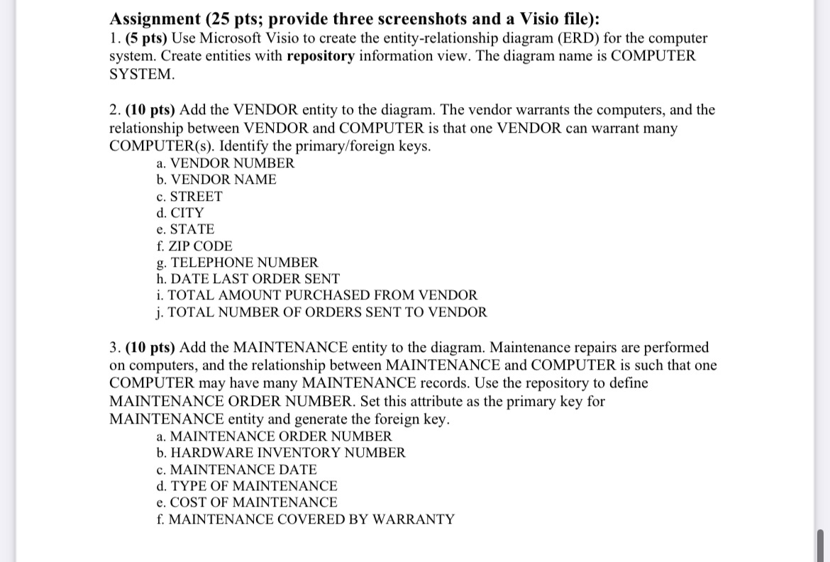
After numerous interviews, prototypes, data flow diagrams, data dictionary entries, and UML diagrams have been completed, Anna and Chip both start work on the entityrelationship model. "I'll be responsible for creating the Microsoft Access table relationships," Anna promises. Chip volunteers to complete an entityrelationship diagram. "Let's compare the two diagrams for accuracy and consistency when we're done," Anna suggests, and so they do
Figure shows the entityrelationship diagram for the computer inventory system. Visible Analyst calls each of the rectangles an entity. Each entity represents a database table of information stored in the system, corresponding to a data store on the data flow diagram or an entity class on a sequence or class diagram.
Each of the diamond rectangles represents an associative entity representing a relationship between the data entities. A rectangle with an oval in it represents an associative entity that cannot exist without the connecting entity. These are usually repeating elements. Microsoft Visio uses rectangles to represent both an associative and an attributive entity.
"I've created the entityrelationship diagram, starting with the simplest portions of the system," Chip tells Anna. "The first data entities created are SOFTWARE and COMPUTER. The relationship is that software is installed on the computer. Next, I determined the cardinality of the relationship. Because one software package could be installed on many computers, this relationship is onetomany. Each computer may also have many different software packages installed on it so that it also provides a onetomany relationship. Because there is a onetomany relationship for each of the data entities, the full relationship between them becomes manytomany."
Chip continues, saying, "This first view is far from normalized. Notice that the SOFTWARE INVENTORY NUMBER is a repeating element on the HARDWARE entity. I will have to create several entities for each of them." A bit later Chip reviews his work with Anna. The SOFTWARE INVENTORY NUMBER has been removed and placed in a relational entity. Refer to the entityrelationship diagram illustrated in Figure "This places the data in the first normal form," remarks Chip. "Also, there are no elements that are dependent on only a part of the key, so the data are also in the second normal form.
There are, however, elements that are not part of the entity that is represented on the diagram, and they will have to be removed. For example, look at OPERATING SYSTEM and CAMPUS BUILDING. These elements are not a part of the computer hardware but are installed on the computer or the computer is installed in a campus room. They should have their own entity. That makes it easier to change the version of an operating system. Rather than having to change the version of the operating system on many of the COMPUTER records, it would only have to be changed once."
Anna agrees, remarking, "That's really a good assessment of the situation. It will make implementing the Microsoft Access tables easier." Chip continues to work on the entityrelationship diagram. After a few hours he exclaims, "I think it's done! Would you take a look at the final version?" The final version is shown in Figure All the entities and relationships have been described in the repository.
Anna reviews the final version and exclaims, It looks great! You are right in moving the OPERATING SYSTEM and CAMPUS BUILDING to their own entities. Good idea, as the
building is not a part of the computer. Also, the SOFTWARE EXPERT is definitely not a part of the SOFTWARE entity. How about the SOFTWARE CATEGORY?"
"I moved the SOFTWARE CATEGORY into its own entity to save room on the master files when they are constructed," Chip answers. It is really a table of codes, and it makes it easy to change the category without changing all of the software records. Also, we are storing a small code, rather than a lengthy description on each software record. Why don't you double check the various keys on the diagram? Each related entity, on the many end, should have a foreign key
change the category without changing all of the software records. Also, we are storing a small code, rather than a lengthy description on each software record. Why don't you double check the various keys on the diagram? Each related entity, on the many end, should have a foreign key that matches the primary key of the entity on the one end."
Anna examines the diagram for a while and remarks, It looks good to me Perhaps we should define the repository entries." "Take a look at this repository entry." Chip opens the entityrelationship diagram, Figure and doubleclicks on the COMPUTERS entity to display its repository entry. The primary key the Microsoft Visio and Visible Analyst PK notation in front of the HARDWARE INVENTORY NUMBER element in the composition area foreign keys the FK FK and so on and several alterna

Step by Step Solution
There are 3 Steps involved in it
Step: 1

Get Instant Access to Expert-Tailored Solutions
See step-by-step solutions with expert insights and AI powered tools for academic success
Step: 2

Step: 3

Ace Your Homework with AI
Get the answers you need in no time with our AI-driven, step-by-step assistance
Get Started


