Answered step by step
Verified Expert Solution
Question
1 Approved Answer
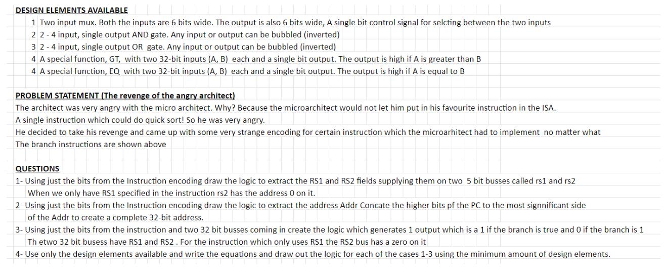
DESIGN ELEMENTS AVAILABLE 1 Two input mux. Both the inputs are 6 bits wide. The output is also 6 bits wide, A single bit


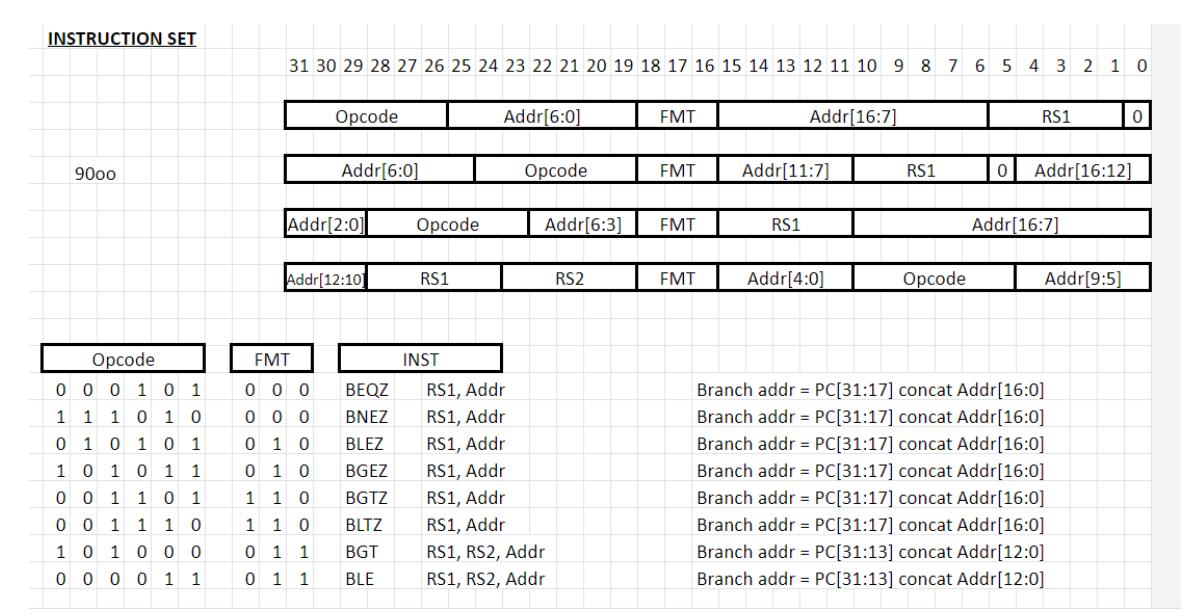
DESIGN ELEMENTS AVAILABLE 1 Two input mux. Both the inputs are 6 bits wide. The output is also 6 bits wide, A single bit control signal for selcting between the two inputs 2 2-4 input, single output AND gate. Any input or output can be bubbled (inverted) 3 2-4 input, single output OR gate. Any input or output can be bubbled (inverted) 4 A special function, GT, with two 32-bit inputs (A, B) each and a single bit output. The output is high if A is greater than B 4 A special function, EQ with two 32-bit inputs (A, B) each and a single bit output. The output is high if A is equal to B PROBLEM STATEMENT (The revenge of the angry architect) The architect was very angry with the micro architect. Why? Because the microarchitect would not let him put in his favourite instruction in the ISA. A single instruction which could do quick sort! So he was very angry. He decided to take his revenge and came up with some very strange encoding for certain instruction which the microarhitect had to implement no matter what The branch instructions are shown above QUESTIONS 1- Using just the bits from the Instruction encoding draw the logic to extract the RS1 and RS2 fields supplying them on two 5 bit busses called rs1 and rs2 When we only have RS1 specified in the instruction rs2 has the address 0 on it. 2- Using just the bits from the Instruction encoding draw the logic to extract the address Addr Concate the higher bits pf the PC to the most significant side of the Addr to create a complete 32-bit address. 3- Using just the bits from the instruction and two 32 bit busses coming in create the logic which generates 1 output which is a 1 if the branch is true and 0 if the branch is 1 Th etwo 32 bit busess have RS1 and RS2. For the instruction which only uses RS1 the RS2 bus has a zero on it 4- Use only the design elements available and write the equations and draw out the logic for each of the cases 1-3 using the minimum amount of design elements. INSTRUCTION SET 9000 Opcode 0 0 0 1 0 1 1 1 1 0 1 0 0 1 0 1 0 1 1 0 1 0 1 1 1 0 0 0 1 1 0 0 0 1 1 1 1 0 1 0 0 0 0 0 0 0 1 1 31 30 29 28 27 26 25 24 23 22 21 20 19 18 17 16 15 14 13 12 11 10 9 8 7 6 5 Opcode Addr[6:0] Addr[2:0] Addr[12:10] FMT 0 1 0 000 BEQZ 000 BNEZ 0 1 0 BLEZ BGEZ BGTZ BLTZ BGT BLE 11 0 1 1 0 011 01 1 Opcode RS1 INST Addr[6:0] Opcode RS1, Addr RS1, Addr RS1, Addr RS1, Addr RS1, Addr RS1, Addr RS1, RS2, Addr RS1, RS2, Addr Addr[6:3] RS2 FMT FMT FMT FMT Addr[16:7] Addr[11:7] RS1 Addr[4:0] RS1 Opcode 4 3 2 1 0 RS1 0 Addr[16:12] Addr[16:7] Addr[9:5] 0 Branch addr PC[31:17] concat Addr[16:0] Branch addr = PC[31:17] concat Addr[16:0] Branch addr PC[31:17] concat Addr[16:0] Branch addr Branch addr PC[31:17] concat Addr[16:0] PC[31:17] concat Addr[16:0] PC[31:17] concat Addr[16:0] Branch addr Branch addr = PC[31:13] concat Addr[12:0] Branch addr = PC[31:13] concat Addr[12:0]
Step by Step Solution
★★★★★
3.43 Rating (153 Votes )
There are 3 Steps involved in it
Step: 1
Answer 1 Using the bits from the Instruction encoding the logic to extract the RS1 and RS2 fields and supply them on two 5 bit busses called rs1 and r...
Get Instant Access to Expert-Tailored Solutions
See step-by-step solutions with expert insights and AI powered tools for academic success
Step: 2

Step: 3

Ace Your Homework with AI
Get the answers you need in no time with our AI-driven, step-by-step assistance
Get Started


