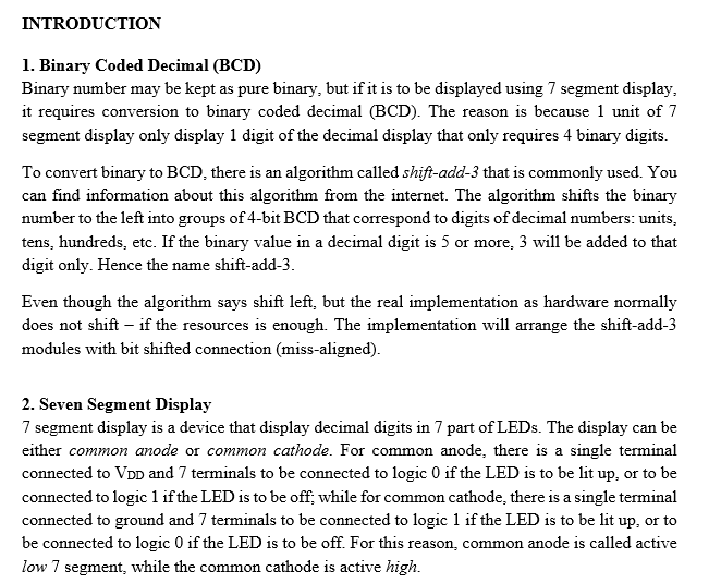
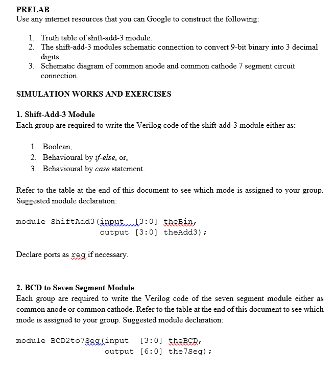
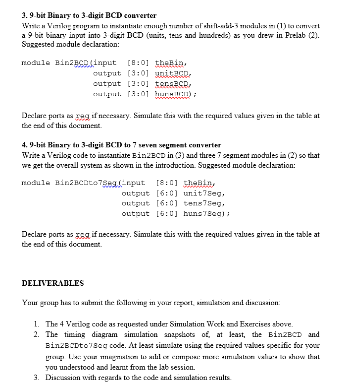

INTRODUCTION 1. Binary Coded Decimal (BCD) Binary number may be kept as pure binary, but if it is to be displayed using 7 segment display, it requires conversion to binary coded decimal (BCD). The reason is because 1 unit of 7 segment display only display 1 digit of the decimal display that only requires 4 binary digits. To convert binary to BCD. there is an algorithm called shift-add-3 that is commonly used. You can find information about this algorithm from the internet. The algorithm shifts the binary number to the left into groups of 4-bit BCD that correspond to digits of decimal numbers: units, tens, hundreds, etc. If the binary value in a decimal digit is 5 or more, 3 will be added to that digit only. Hence the name shift-add-3. Even though the algorithm says shift left, but the real implementation as hardware normally does not shift if the resources is enough. The implementation will arrange the shift-add-3 modules with bit shifted connection (miss-aligned). 2. Seven Segment Display 7 segment display is a device that display decimal digits in 7 part of LEDs. The display can be either common anode or common cathode. For common anode, there is a single terminal connected to VoD and 7 terminals to be connected to logic 0 if the LED is to be lit up, or to be connected to logic 1 if the LED is to be off, while for common cathode, there is a single terminal connected to ground and 7 terminals to be connected to logic 1 if the LED is to be lit up, or to be connected to logic 0 if the LED is to be off. For this reason, common anode is called active low 7 segment, while the common cathode is active high. PRELAB Use any internet resources that you can Google to construct the following: 1. Truth table of shift-add-3 module. 2. The shift-add-3 modules schematic connection to convert 9-bit binary into 3 decimal digits. 3. Schematic diagram of common anode and common cathode 7 segment circuit connection. SIMULATION WORKS AND EXERCISES 1. Shift-Add-3 Module Each group are required to write the Verilog code of the shift-add-3 module either as: 1. Boolean, 2. Behavioural by if-else, or, 3. Behavioural by case statement. Refer to the table at the end of this document to see which mode is assigned to your group. Suggested module declaration: module shiftAdd3 (input(3:0) thebin, output [3:0] theAdd3); Declare ports as reg if necessary. 2. BCD to Seven Segment Module Each group are required to write the Verilog code of the seven segment module either as common anode or common cathode. Refer to the table at the end of this document to see which mode is assigned to your group. Suggested module declaration: module BCD2 to 7Seg(input [3:0] theBCD, output [6:0] the 7Seg); 3. 9-bit Binary to 3-digit BCD converter Write a Verilog program to instantiate enough number of shift-add-3 modules in (1) to convert a 9-bit binary input into 3-digit BCD (units, tens and hundreds) as you drew in Prelab (2). Suggested module declaration: module Bin2BCD.(input [8:0] theBin, output [3:0] unitBCD, output [3:0] tensBCD, output [3:0] hunsBCD); Declare ports as reg if necessary. Simulate this with the required values given in the table at the end of this document. 4.9-bit Binary to 3-digit BCD to 7 seven segment converter Write a Verilog code to instantiate Bin2BCD in (3) and three 7 segment modules in (2) so that we get the overall system as shown in the introduction. Suggested module declaration: module Bin2BCDto7Seg (input [8:0] theBin, output [6:0] unit7Seg, output [6:0] tens 7 Seg, output (6:0) huns 7 Seg); Declare ports as reg if necessary. Simulate this with the required values given in the table at the end of this document. DELIVERABLES Your group has to submit the following in your report, simulation and discussion: 1. The 4 Verilog code as requested under Simulation Work and Exercises above. 2. The timing diagram simulation snapshots of at least, the Bin2BCD and Bin2BCDto7Seg code. At least simulate using the required values specific for your group. Use your imagination to add or compose more simulation values to show that you understood and learnt from the lab session. 3. Discussion with regards to the code and simulation results. Boolean Active Low 9, 70, 202 INTRODUCTION 1. Binary Coded Decimal (BCD) Binary number may be kept as pure binary, but if it is to be displayed using 7 segment display, it requires conversion to binary coded decimal (BCD). The reason is because 1 unit of 7 segment display only display 1 digit of the decimal display that only requires 4 binary digits. To convert binary to BCD. there is an algorithm called shift-add-3 that is commonly used. You can find information about this algorithm from the internet. The algorithm shifts the binary number to the left into groups of 4-bit BCD that correspond to digits of decimal numbers: units, tens, hundreds, etc. If the binary value in a decimal digit is 5 or more, 3 will be added to that digit only. Hence the name shift-add-3. Even though the algorithm says shift left, but the real implementation as hardware normally does not shift if the resources is enough. The implementation will arrange the shift-add-3 modules with bit shifted connection (miss-aligned). 2. Seven Segment Display 7 segment display is a device that display decimal digits in 7 part of LEDs. The display can be either common anode or common cathode. For common anode, there is a single terminal connected to VoD and 7 terminals to be connected to logic 0 if the LED is to be lit up, or to be connected to logic 1 if the LED is to be off, while for common cathode, there is a single terminal connected to ground and 7 terminals to be connected to logic 1 if the LED is to be lit up, or to be connected to logic 0 if the LED is to be off. For this reason, common anode is called active low 7 segment, while the common cathode is active high. PRELAB Use any internet resources that you can Google to construct the following: 1. Truth table of shift-add-3 module. 2. The shift-add-3 modules schematic connection to convert 9-bit binary into 3 decimal digits. 3. Schematic diagram of common anode and common cathode 7 segment circuit connection. SIMULATION WORKS AND EXERCISES 1. Shift-Add-3 Module Each group are required to write the Verilog code of the shift-add-3 module either as: 1. Boolean, 2. Behavioural by if-else, or, 3. Behavioural by case statement. Refer to the table at the end of this document to see which mode is assigned to your group. Suggested module declaration: module shiftAdd3 (input(3:0) thebin, output [3:0] theAdd3); Declare ports as reg if necessary. 2. BCD to Seven Segment Module Each group are required to write the Verilog code of the seven segment module either as common anode or common cathode. Refer to the table at the end of this document to see which mode is assigned to your group. Suggested module declaration: module BCD2 to 7Seg(input [3:0] theBCD, output [6:0] the 7Seg); 3. 9-bit Binary to 3-digit BCD converter Write a Verilog program to instantiate enough number of shift-add-3 modules in (1) to convert a 9-bit binary input into 3-digit BCD (units, tens and hundreds) as you drew in Prelab (2). Suggested module declaration: module Bin2BCD.(input [8:0] theBin, output [3:0] unitBCD, output [3:0] tensBCD, output [3:0] hunsBCD); Declare ports as reg if necessary. Simulate this with the required values given in the table at the end of this document. 4.9-bit Binary to 3-digit BCD to 7 seven segment converter Write a Verilog code to instantiate Bin2BCD in (3) and three 7 segment modules in (2) so that we get the overall system as shown in the introduction. Suggested module declaration: module Bin2BCDto7Seg (input [8:0] theBin, output [6:0] unit7Seg, output [6:0] tens 7 Seg, output (6:0) huns 7 Seg); Declare ports as reg if necessary. Simulate this with the required values given in the table at the end of this document. DELIVERABLES Your group has to submit the following in your report, simulation and discussion: 1. The 4 Verilog code as requested under Simulation Work and Exercises above. 2. The timing diagram simulation snapshots of at least, the Bin2BCD and Bin2BCDto7Seg code. At least simulate using the required values specific for your group. Use your imagination to add or compose more simulation values to show that you understood and learnt from the lab session. 3. Discussion with regards to the code and simulation results. Boolean Active Low 9, 70, 202