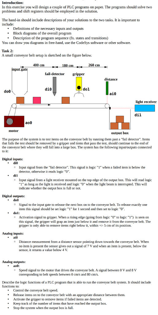
Introduction In this exercise you will design a couple of PLC programs on paper. The programs should solve two problems and shift registers should be employed in the solution. The hand-in should include descriptions of your solutions to the two tasks. It is important to include: .Definitions of the necessary inputs and outputs .Block diagrams of the overall program You can draw you diagrams in free-hand, use the CodeSys software or other software Task 2: A small conveyor belt setup is sketched on the figure below. Description of the program sequence (fx. states and transitions) 400 cm 260 cm ut fail-detector gripper distance do1 doo light receiver a08 motor output box The purpose of the system is to test items on the conveyor belt by running them past a "fail detector". Items that fails the test should be removed by a gripper and items that pass the test, should continue to the end of the conveyor belt where they will fall into a large box. The system has the following input/outputs connected to it: Digital inputs: di0 o Input signal from the "fail detector". This signal is logic 1" when a failed item is below the detector, otherwise it reads logic "O", di1 o Input signal from a light receiver mounted on the top edge of the output box. This will read logic "1" as long as the light is received and logic "O" when the light beam is interrupted. This will indicate whether the output box is full or not. Digital outputs: do0 Signal to the input gate to release the next box on to the conveyor belt. To release exactly one item this signal should be set logic "1" for 1 second and then set to logic "O". do1 o Activation signal to gripper. When a rising edge (going from logic "O" to logic "1") is seen on this signal, the gripper will grap an item just below it and remove it from the conveyor belt. The gripper is only able to remove items right below it, within +5 cm of its position. Analog inputs: ai0 o Distance measurement from a distance sensor pointing down towards the conveyor belt. When no item is present the sensor gives out a signal of 7 V and when an item is present, below the sensor, it returns a value below 4 V. Analog outputs: ao0: Speed signal to the motor that drives the conveyor belt. A signal between 0 V and 8 V corresponding to belt speeds between 0 cm/s and 80 cm's. o Describe the logic functions of a PLC program that is able to run the conveyor belt system. It should include functions to: Control the conveyor belt speed. Release items on to the conveyor belt with an appropriate distance between them. Activate the gripper to remove items if failed items are detected Keep track of the number of items that have reached the output box . .Stop the system when the output box is full Introduction In this exercise you will design a couple of PLC programs on paper. The programs should solve two problems and shift registers should be employed in the solution. The hand-in should include descriptions of your solutions to the two tasks. It is important to include: .Definitions of the necessary inputs and outputs .Block diagrams of the overall program You can draw you diagrams in free-hand, use the CodeSys software or other software Task 2: A small conveyor belt setup is sketched on the figure below. Description of the program sequence (fx. states and transitions) 400 cm 260 cm ut fail-detector gripper distance do1 doo light receiver a08 motor output box The purpose of the system is to test items on the conveyor belt by running them past a "fail detector". Items that fails the test should be removed by a gripper and items that pass the test, should continue to the end of the conveyor belt where they will fall into a large box. The system has the following input/outputs connected to it: Digital inputs: di0 o Input signal from the "fail detector". This signal is logic 1" when a failed item is below the detector, otherwise it reads logic "O", di1 o Input signal from a light receiver mounted on the top edge of the output box. This will read logic "1" as long as the light is received and logic "O" when the light beam is interrupted. This will indicate whether the output box is full or not. Digital outputs: do0 Signal to the input gate to release the next box on to the conveyor belt. To release exactly one item this signal should be set logic "1" for 1 second and then set to logic "O". do1 o Activation signal to gripper. When a rising edge (going from logic "O" to logic "1") is seen on this signal, the gripper will grap an item just below it and remove it from the conveyor belt. The gripper is only able to remove items right below it, within +5 cm of its position. Analog inputs: ai0 o Distance measurement from a distance sensor pointing down towards the conveyor belt. When no item is present the sensor gives out a signal of 7 V and when an item is present, below the sensor, it returns a value below 4 V. Analog outputs: ao0: Speed signal to the motor that drives the conveyor belt. A signal between 0 V and 8 V corresponding to belt speeds between 0 cm/s and 80 cm's. o Describe the logic functions of a PLC program that is able to run the conveyor belt system. It should include functions to: Control the conveyor belt speed. Release items on to the conveyor belt with an appropriate distance between them. Activate the gripper to remove items if failed items are detected Keep track of the number of items that have reached the output box . .Stop the system when the output box is full