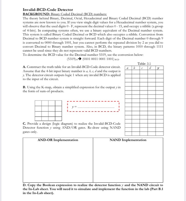
Question: Invalid-BCD-Code Detector BACKGROUND: Binary Coded Decimal (BCD) numbers: The theory behind Binary, Decimal, Octal, Hexadecimal and Binary Coded Decimal (BCD) number systems are now

Invalid-BCD-Code Detector BACKGROUND: Binary Coded Decimal (BCD) numbers: The theory behind Binary, Decimal, Octal, Hexadecimal and Binary Coded Decimal (BCD) number systems are now known to you. If you view single digit values for a Hexadecimal number system, you will observe that the used digits 0-F, represent the decimal values 0-15, and occupy a nibble (a group of 4-bits). In computing systems often, we use a binary equivalent of the Decimal number system. This system is called Binary Coded Decimal or BCD which also occupies a nibble. Conversion from Decimal to BCD number system is straight forward. Each digit of the Decimal number 0 through 9 is converted to 0000 through 1001, but you cannot perform the repeated division by 2 as you did to convert Decimal to Binary number system. Also, in BCD, the binary patterns 1010 through 1111 cannot be used since they do not represent valid BCD numbers. To determine the BCD value for the Decimal number 5319, see the conversion below: (5319) (0101 0011 0001 1001) BCD A. Construct the truth table for an Invalid-BCD-Code detector circuit. Assume that the 4-bit input binary number is a, b, c, d and the output is J. The detector circuit outputs logic 1 when any invalid BCD is applied to the input of the circuit. B. Using the K-map, obtain a simplified expression for the output y in the form of sum-of-products. I y= C. Provide a design (logic diagram) to realize the Invalid-BCD-Code Detector function y using AND/OR gates. Re-draw using NAND gates only. AND-OR Implementation b Table: 3.1 ( 2 NAND Implementation D. Copy the Boolean expression to realize the detector function y and the NAND circuit to the In-Lab sheet. You will need it to simulate and implement the function in the lab (Part B.1 in the In-Lab sheet).
Step by Step Solution
3.46 Rating (156 Votes )
There are 3 Steps involved in it
A Truth ta... View full answer

Get step-by-step solutions from verified subject matter experts


