Answered step by step
Verified Expert Solution
Question
1 Approved Answer
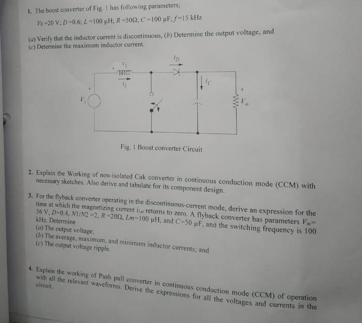
1. The boost converter of Fig. I has following parameters; Vs-20 V: D-0.6; L-100 H; R-5022; C-100 uF; f-15 kHz (a) Verify that the

1. The boost converter of Fig. I has following parameters; Vs-20 V: D-0.6; L-100 H; R-5022; C-100 uF; f-15 kHz (a) Verify that the inductor current is discontinuous, (b) Determine the output voltage, and (c) Determine the maximum inductor current. Fig. 1 Boost converter Circuit tc 2. Explain the Working of non-isolated Cuk converter in continuous conduction mode (CCM) with necessary sketches. Also derive and tabulate for its component design. 3. For the flyback converter operating in the discontinuous-current mode, derive an expression for the time at which the magnetizing current it returns to zero. A flyback converter has parameters Vi= 36 V, D-0.4, N1/N2-2, R 2002, Lm-100 uH, and C-50 F, and the switching frequency is 100 kHz. Determine (a) The output voltage: (b) The average, maximum, and minimum inductor currents; and (c) The output voltage ripple. 4. Explain the working of Push pull converter in continuous conduction mode (CCM) of operation with all the relevant waveforms. Derive the expressions for all the voltages and currents in the circuit.
Step by Step Solution
★★★★★
3.48 Rating (155 Votes )
There are 3 Steps involved in it
Step: 1
a Verify that the inductor current is discontinuous To verify that the inductor current is discontinuous we can check the following condition L Vin D2 Ts 2 R where L is the inductor value Vin is the i...
Get Instant Access to Expert-Tailored Solutions
See step-by-step solutions with expert insights and AI powered tools for academic success
Step: 2

Step: 3

Ace Your Homework with AI
Get the answers you need in no time with our AI-driven, step-by-step assistance
Get Started


