

Answered step by step
Verified Expert Solution
Question
1 Approved Answer
I've been trying for hours trying to understand. Thanks for the help! Your task is to use a funnel shifter to create a programmable shift
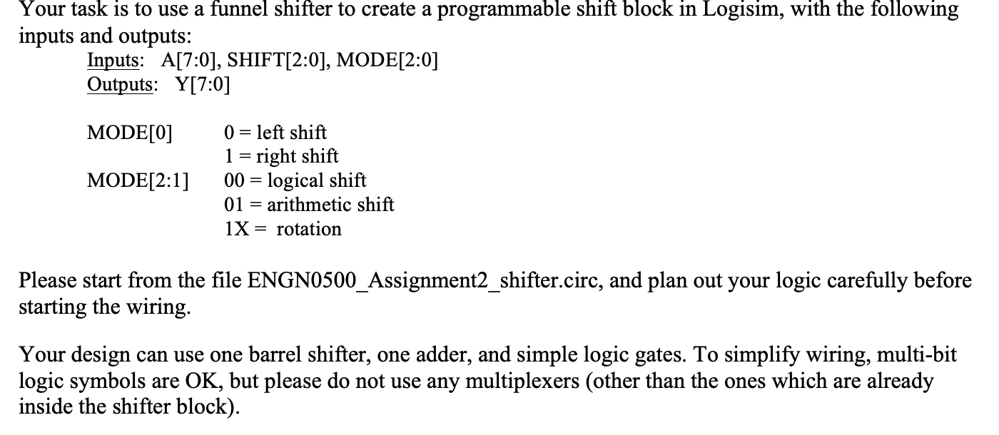
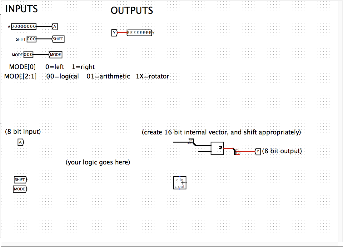 I've been trying for hours trying to understand. Thanks for the help!
Step by Step Solution
There are 3 Steps involved in it
Step: 1

Get Instant Access to Expert-Tailored Solutions
See step-by-step solutions with expert insights and AI powered tools for academic success
Step: 2

Step: 3
Ace Your Homework with AI
Get the answers you need in no time with our AI-driven, step-by-step assistance
Get Started
Database Programming Languages 12th International Symposium Dbpl 2009 Lyon France August 2009 Proceedings Lncs 5708
Authors: Philippa Gardner ,Floris Geerts
2009th Edition
3642037925, 978-3642037924